7. Advanced Features
7.1. Device Register Access
Ethernet PHYs and switches contain many status and configuration registers. The method in which these registers are accessed depend on both the device and decisions made during the electrical design of the product. Intrepid products access PHY and Switch registers either using MDIO or SPI interfaces. The table below lists the Ethernet devices contained in your product along with the management interface information needed to access a device’s registers using Vehicle Spy or Intrepid’s Open Source API.
7.1.1. Ethernet Device Register Interfaces
The MDIO addressing for Ethernet ports of of the RAD-Comet are as follows.
Device |
Port |
MDIO Bus Index |
PHY Address |
Protocol |
RAD-Comet |
Ethernet (100/1000BASE-T) |
0x01 |
0x01 |
Clause 22 |
AE-01 (100BASE-T1) |
0x02 |
0x02 |
Clause 45 |
|
AE-02 (10BASE-T1S) |
0x03 |
0x00 |
Clause 22 |
7.1.2. MDIO Protocol
This section provides an introduction and overview of the MDIO protocol.
Already familiar with MDIO?
If this information is not needed, skip to the following sections for instruction on how to use this protocol with Vehicle Spy or Intrepid’s Open Source API.
Each MDIO frame is 32 bits:
2 start bits
2 bit operation code
5 bit phy address
5 bit register address
2 bit turn around delay
16 bits of data.
As Ethernet devices has evolved over the years, so has the protocol used to communicate with them. Devices in Intrepid products use either Clause 22 or Clause 45, which will be explained in the following sections.
Clause 22
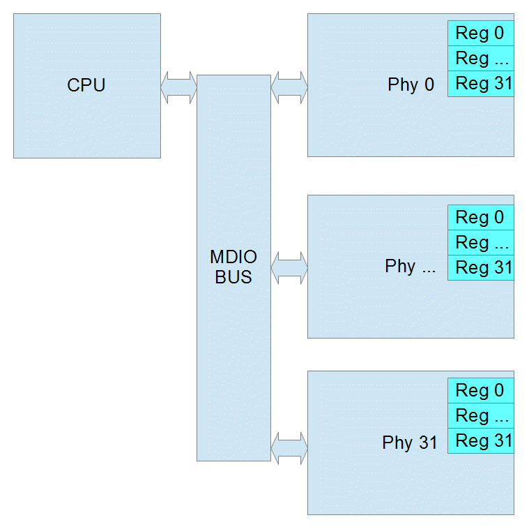
The initial protocol, IEEE 802.3 Clause 22, was designed to read or write 32 registers within 32 devices. Each read/write is done in one operation.
Phy Address 5 bits (0 – 31 decimal)
Register address 5 bits (0 – 31 decimal) or (0 – 1F hex)
Data 16 bits

Page Register
Some Ethernet Phy manufacturers added a page register to allow for more registers in Clause 22. The page can be 0 – 255 decimal. If the Phy does not support pages, then page will be ignored. When using pages, reads and writes can no longer be performed in one operation. Instead you must write to the page register and then before any other process changes the page, you can read or write the destination register. If another process were to change the page register before you finish, the result will be an read the wrong register or an write to wrong register which may cause the Phy to stop working.
Common Clause 22 Registers
Clasuse 22 Registers |
Bits |
Function/Status |
|
|---|---|---|---|
Control Register (Register 0) |
15 |
reset |
|
14 |
loopback |
||
12 |
auto negotiate |
||
11 |
power down |
||
10 |
isolate |
||
9 |
renegotiate |
||
8 |
duplex |
||
7 |
collision test |
||
6/13 |
speed |
10=1000mbps |
|
01=100mbps |
|||
00=10mbps |
|||
Status Register (Register 1) |
5 |
Auto Negotiation Complete |
|
4 |
Remote Fault |
||
3 |
Auto Negotiation Capability |
||
2 |
Link Status |
||
1 |
Jabber Detect |
||
0 |
Extended Capability |
||
Phy ID Reg 1 (Register 2) |
15:0 |
OUI MSB |
|
PHY ID Reg 2 (Register 1) |
15:10 |
OUI LSB |
|
9:4 |
Model Number |
||
3:0 |
Revision Number |
||
Clause 45
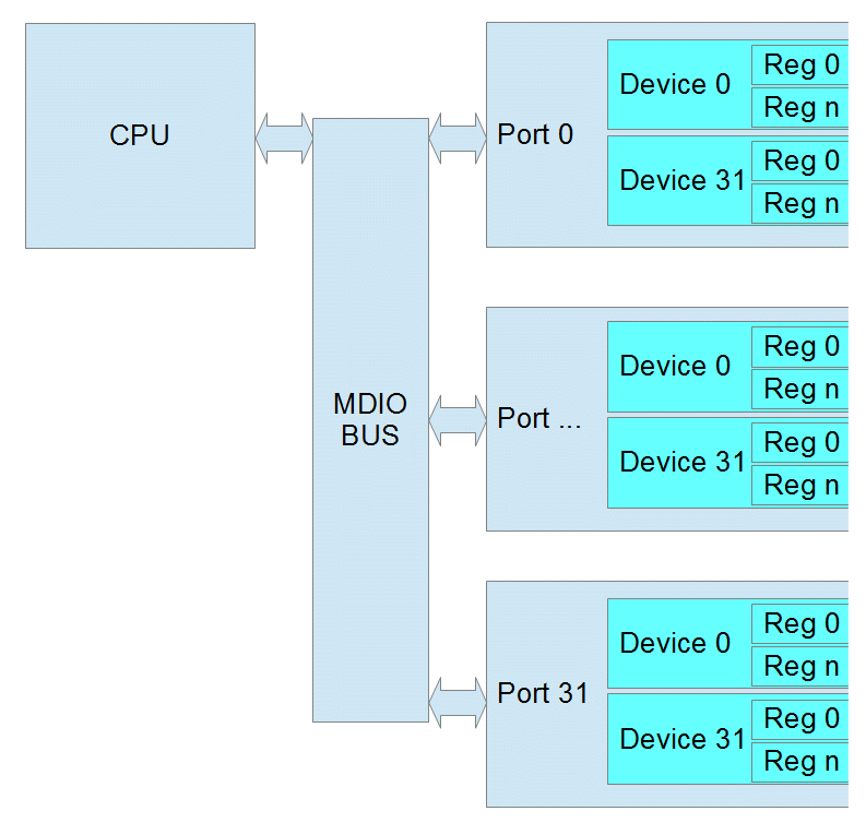
As Ethernet Phys became more complicated and supported different speeds and connections, IEEE 802.3 Clause 45 was added. Because the Register Address is now 16 bits, each read/write takes at 2 operations. The first operation is always writing the Register Address that you want to use in the next operation. The second is the actual read or write. There is also a special read that increments the address after each read which allows you to write a starting address and then read a whole block of registers.
Port 5 bits (this is equivalent to the Phy Address)
Device 5 bits (this is similar to the page)
Register address 16 bits (this allows 65536 registers in each device)
Data 16 bits

Common Clause 45 Registers
PMA/PMD Registers
Device |
Register |
Bits |
Function/Status |
||
Control Register |
1 |
0 |
15 |
reset |
|
11 |
power down |
||||
6/13 |
speed (10-1000mbps) |
11=Speed set by bits 5:2 |
|||
10=1000mbps |
|||||
01=100mbps |
|||||
00=10mbps |
|||||
5:2 |
speed (2.5-10 Gbps) |
0111=5 Gbps |
|||
0110=2.5 Gbps |
|||||
0000=10 Gbps |
|||||
Device ID Reg 1 |
1 |
2 |
15:0 |
Auto Negotiation Complete |
|
Device ID Reg 2 |
1 |
3 |
15:10 |
OUI LSB |
|
9:4 |
Model Number |
||||
3:0 |
Revision Number |
||||
PCS Registers
Device |
Register |
Bits |
Function/Status |
||
|---|---|---|---|---|---|
Control Register |
3 |
0 |
15 |
reset |
|
14 |
loopback |
||||
11 |
power down |
||||
6/13 |
speed |
10=1000mbps |
|||
01=100mbps |
|||||
00=10mbps |
|||||
Device ID Reg 1 |
3 |
2 |
15:0 |
Auto Negotiation Complete |
|
Device ID Reg 2 |
3 |
3 |
15:10 |
OUI LSB |
|
9:4 |
Model Number |
||||
3:0 |
Revision Number |
||||
7.1.3. Using MDIO with Intrepid Devices
MDIO access to Registers in Intrepid devices can be accomplishes using:
libicsneo , the Intrepid Control Systems cross-platform device communication library. Installation and usage documentation for libicsneo can be found within each of the respective APIs.
The following sections provide examples for each method of MDIO register access.
Vehicle Spy 3 Software MDIO Example
Coming Soon!
C++ MDIO Example:
The following code block is an example of writing and reading to a register using the C++ API.
// We can transmit messages to write to arbitrary register
std::cout << "\tTransmitting a MDIO request to write register on 88Q2112...\n";
mdio_r = std::make_shared<icsneo::MDIOMessage>();
mdio_r->network = icsneo::Network::NetID::MDIO1;
mdio_r->phyAddress = 0x06u;
mdio_r->devAddress = 0x01u;
mdio_r->regAddress = 0x0902u;
mdio_r->data = {0xA3, 0x02};
mdio_r->direction = icsneo::MDIOMessage::Direction::Write;
mdio_r->clause = icsneo::MDIOMessage::Clause::Clause45;
ret = device->transmit(mdio_r); // This will return false if the device does not support MDIO
std::cout << (ret ? "OK" : "FAIL") << std::endl;

// We can transmit messages to read back to arbitrary register
std::cout << "\tTransmitting a MDIO request to read register on 88Q2112...\n";
mdio_r = std::make_shared<icsneo::MDIOMessage>();
mdio_r->network = icsneo::Network::NetID::MDIO1;
mdio_r->phyAddress = 0x06u;
mdio_r->devAddress = 0x01u;
mdio_r->regAddress = 0x0902u;
mdio_r->direction = icsneo::MDIOMessage::Direction::Read;
mdio_r->clause = icsneo::MDIOMessage::Clause::Clause45;
ret = device->transmit(mdio_r); // This will return false if the device does not support MDIO
std::cout << (ret ? "OK" : "FAIL") << std::endl;
An complete example of how to use MDIO through the C++ API can be found here: MDIO C++ Example
Python MDIO Example:
The following code block is an example of writing and reading to a register using the Python API.
import icsneopy

a = icsneopy.MDIOMessage()
a.network = icsneopy.Network(icsneopy.Network.NetID.MDIO1)
a.phyAddress = 0x00
a.regAddress = 0x02
a.direction = icsneopy.MDIOMessage.Direction.Read
a.clause = icsneopy.MDIOMessage.Clause.Clause22
dev.transmit(a)

b = icsneopy.MDIOMessage()
b.network = icsneopy.Network(icsneopy.Network.NetID.MDIO1)
b.phyAddress = 0x00
b.regAddress = 0x18
b.direction = icsneopy.MDIOMessage.Direction.Write
b.clause = icsneopy.MDIOMessage.Clause.Clause22
dev.transmit(b)
C MDIO Example
Coming Soon!
7.1.4. Using SPI with Intrepid Products
SPI access to Registers in Intrepid devices can be accomplishes using:
libicsneo , the Intrepid Control Systems cross-platform device communication library. Installation and usage documentation for libicsneo can be found within each of the respective APIs.
The following sections provide examples for each method of SPI register access.
Vehicle Spy 3 Software SPI Example
Coming Soon!
C++ SPI Example:
The following code block is an example of writing and reading to a register using the C++ API.
// Coming Soon!!
An complete example of how to use MDIO through the C++ API can be found here: MDIO C++ Example
Python SPI Example:
The following code block is an example of writing and reading to a register using the Python API.
# Coming Soon!!
C SPI Example
// Coming Soon!!
7.1.5. Vehicle Spy’s PHY Dashboard
PHY Dashboard is a feature of Vehicle Spy 3 allowing simple device register reads and writes using MDIO.
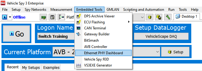
Opening the PHY Dashboard
The PHY Dashboard can be opened from the Embedded Tools menu in Vehicle Spy (shown below)

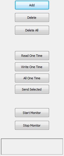
PHY Dashboard Interface
Add – use this button to add MDIO operations. Ctrl-S saves screen contents to VS3 file.
Delete – deletes the currently selected item or item.
Delete All – deletes all operations
Read One Time – performs all reads from the list once. No writes are performed.
Write One Time – performs all writes from the list once. No reads are performed.
All One Time – performs every item in the list once.
Send Selected – performs only the selected item or items once.
Start Monitor – performs all reads once per second.
Stops Monitor – stops the monitor operation.
Note: all values in Hex except Phy Address/Port

PHY Dashboard Examples
Clause 22 Example:

Line 1 writes soft reset to phy address 16, using Clause 22
Line 2 reads Phy ID Reg1 from phy address 16 using Clause 22
Line 3 reads Phy ID Reg2 from phy address 16 using Clause 22
Clause 45 Example:

Line 1 writes soft reset of PCS to Port 16, Device 3 using Clause 45
Line 2 reads PCS ID Reg1 from Port 16, Device 3 using Clause 45
Line 3 reads PCS ID Reg2 from Port 16, Device 3 using Clause 45
MDIO Addresses for your hardware
Reference this MDIO address table for the addresses specific to your hardware.