3. A Tour of RAD-Moon T1S Hardware
3.1. Label and Status Indicators
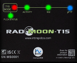
3.1.1. 10BASE-T1S Status Information
The status of the 10BASE-T1 port is displayed in the 5 LEDs seen above.
LED |
Color |
Indication |
T1S MODE |
|
PLCA Coordinator |
|
PLCA Follower |
|
|
Multiple Node IDs Assigned |
|
|
CSMA/CD Mode |
|
ACTIVITY |
|
Frame Transmitted |
|
Frame Received |
|
|
Error (e.g. Bad CRC, PLCA error) |
|
SQI |
|
BER > 10e-10 |
|
BER < 10e-10 |
|
|
||
gPTP |
|
Disabled |
|
Solid - Leader |
|
Slow Blink - Follower (Not Locked) |
||
Fast Blink - Follower (Locked) |
||
PLCA STATUS |
|
BEACON present |
|
Collision |
|
|
Jabber |
|
|
Unexpected BEACON |
|
|
Empty Cycle |
|
|
RX in Transmit Opportunity |
10BASE-T1S SQI
Note that SQI measurements on 10BASE-T1S networks require network traffic to be present.
3.1.2. Bootloader Mode
You may see all the LEDs on the top label flashing synchronously. This means the device is in bootloader mode, which should only happen when flashing the device’s firmware. If this is observed unexpectedly or following a firmware update, please contact customer support for assistance.
3.1.3. Device Configuration using Membrane Buttons
Note:
The settings described in this section can also be modified using neoVI Explorer or Intrepid’s open source cross-platform device communication API. (explained later in this guide)
Entering Configuration Mode
The PLCA Node ID and Max Nodes can be changed using the membrane buttons on the top of the RAD-Moon T1S.
To enter configuration mode hold the  button for 3 seconds. This button
is underneath the Intrepid logo on the bottom/center of the top label.
button for 3 seconds. This button
is underneath the Intrepid logo on the bottom/center of the top label.
The PLCA Status LED indicates when the RAD-Moon T1S is in configuration mode and which PLCA setting can be changed.
PLCA Status LED |
|
White |
Node ID Configuration |
Flashing White/Blue |
Max Node Configuration |
Momentarily pressing the button (less than 3 seconds) alternates between these two configuration modes.
Changing NODE ID (White PLCA Status)
If the PLCA Status LED is white, the Node ID is represented by the LEDs
as shown in the following table. Pressing the  button cycles
through the configurations of the table.
button cycles
through the configurations of the table.
T1S MODE |
Activity |
SQI |
gPTP |
|
0 |
|
|
|
|
1 |
|
|
|
|
2 |
|
|
|
|
3 |
|
|
|
|
4 |
|
|
|
|
5 |
|
|
|
|
6 |
|
|
|
|
7 |
|
|
|
|
8 |
|
|
|
|
9 |
|
|
|
|
10 |
|
|
|
|
11 |
|
|
|
|
12 |
|
|
|
|
13 |
|
|
|
|
14 |
|
|
|
|
15 |
|
|
|
|
CSMA/CD |
|
|
|
|
Multi-Node |
|
|
|
|
Multiple Node IDs
A magenta
LED indicates that there is more than one PLCA Node ID assigned to the 10BASE-T1S port.This multi-node ID assignment can only be done by changing the 10BASE-T1S PHY Settings using the neoVI Explorer Configuration Utility.
Any changes to the node ID using the membrane buttons will result in a single node ID assigned.
Changing Max Nodes (Alternating White/Blue PLCA Status)
T1S MODE |
Activity |
SQI |
gPTP |
|
1 |
|
|
|
|
2 |
|
|
|
|
3 |
|
|
|
|
4 |
|
|
|
|
5 |
|
|
|
|
6 |
|
|
|
|
7 |
|
|
|
|
8 |
|
|
|
|
9 |
|
|
|
|
10 |
|
|
|
|
11 |
|
|
|
|
12 |
|
|
|
|
13 |
|
|
|
|
14 |
|
|
|
|
15 |
|
|
|
|
Exiting Configuration Mode
Configuration mode can be exited by holding the button for 3 seconds or cycling power to the device.
3.2. Connector Interfaces
3.2.1. Power/USB/1000BASE-T Interfaces
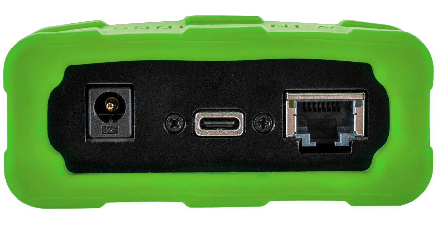
Barrel Jack (Left):
The device can be powered using a DC supply between 5.5-40V volts with a minimum power of 10 Watts. Using a power supply that does not meet these requirements may cause the device to malfunction or be permanently damaged.
USB Type C (Center):
This serves as a connection to a host computer for configuration, firmware updates, and PHY register access.
Note
RAD-Moon T1S cannot be powered by the USB connection.
Ethernet (Right)
The industry standard RJ-45 Ethernet jack is a 100/1000BASE-T port that can be bridged to the 10BASE-T1S port or used independently for sending and receiving Ethernet traffic with Vehicle Spy 3 software or an application written using Intrepid’s Open Source API .
Vehicle Spy, an coremini script or an application wrote with Intrepid’s Open Source API
Link LED (Green): Indicates that a valid link has been established between your device and another 100/1000 Ethernet device.
Activity LED (Orange): Flashes when traffic passes in either direction over the attached Ethernet cable.
In normal operation you should see the Link LED always on, and the Activity LED flashing at a variable rate, with faster flashing meaning that more data is being transferred.
3.2.2. 10BASE-T1S Interface
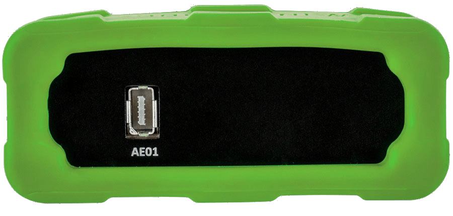
The IX connector on this end of the RAD-Moon T1S contains a single 10BASE-T1S ports that can be bridged to the 100/1000BASE-T port or used independently for sending and receiving Ethernet traffic with Vehicle Spy 3 software or an application written using Intrepid’s Open Source API .
PIN |
FUNCTION |
Cable Color |
1 |
AE_01_P |
white/orange |
2 |
AE_01_N |
orange |
3 |
GND |
– |
4 |
NC |
blue |
5 |
NC |
white/blue |
6 |
NC |
white/green |
7 |
NC |
green |
8 |
GND |
– |
9 |
NC |
white/brown |
10 |
NC |
brown |