3. A Tour of RAD-Epsilon XL Hardware
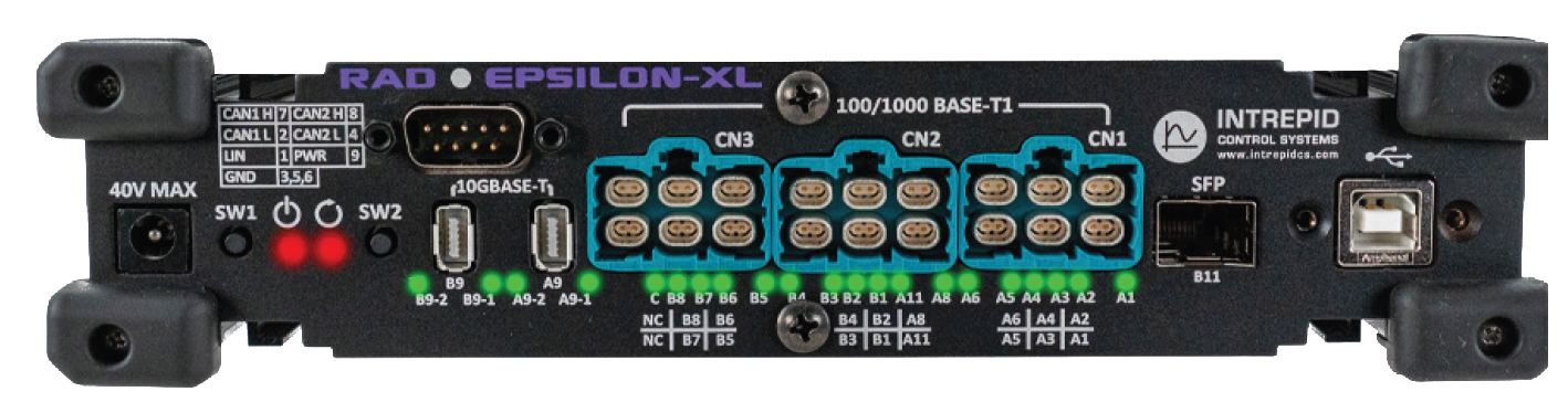
Before learning how to configure and set up the device, let’s examine the device’s front panel from left to right to understand all of its interfaces and status indicators.
3.1. Barrel Jack
RAD Epsilon XL can be powered by the 2.1 mm barrel jack on the left of the front panel. See this section for the power requirements.
3.2. LED Status Indicators
3.2.1.  Power/Status
Color |
State |
|---|---|
|
Device is Powered |
|
Connected to USB host |
|
Online with VSPY |
![]() Status
Status
Color |
State |
|---|---|
|
Embedded Script Running |
note
SW1 and SW2 are mechanical buttons intended for future use and currently have no function.
3.3. DB9 Connector (CAN/LIN):
The DB9 is both a power connector as well as contains the CAN FD and LIN networks.
Pin |
Signal |
Pin |
Signal |
|
1 |
LIN |
6 |
GND |
|
2 |
CAN 1 L |
7 |
CAN 1 H |
|
3 |
GND |
8 |
CAN 2 H |
|
4 |
CAN 2 L |
9 |
VBATT |
|
5 |
GND |
|||
3.4. 10GBASE-T Ports (A9/B9)
The RAD Epsilon uses IX Connectors for two 10GBASE-T Ports.
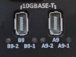
The link speed and status are reported by the LEDs as follows.
B9-2/A9-2 Link Status |
Inactive |
Link Inactive |
Solid |
Link Active |
|
Flashing |
RX/TX Activity |
|
B9-1/A9-1 Link Speed |
Inactive |
Link Inactive |
1x Flash |
10 Mbps |
|
2x Flash |
100 Mbps |
|
3x Flash |
1000 Mbps |
|
4x Flash |
10 Gbps |
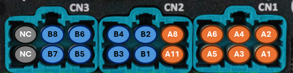
3.5. 100/1000BASE-T1 Ports
The 100/1000BASE-T1 ports are contained in the 3 H-MTD connectors in the center of the face plate.
3.5.1. Connector Cavity Assignments
The port assignments can be seen below.
3.5.2. Terminal Pin Indexing
The pin assignments in each connector cavity can be found in the table below (looking into the connector )
Left Pin |
Right Pin |
|---|---|
1000BASE-T1_N |
1000BASE-T1_P |
3.5.3. Status LEDs
Below the H-MTD Connectors, CN1/CN2/CN2, is a row of LEDs to indicate the status of the 1000BASE-T1 Ports. Each LED is labeled with the associated switch port. Below the LEDs is a legend of where a switch port resides in the connector above.
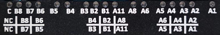
The LEDs indicate the state of the port as follows.
Off |
Link Down |
Solid Green |
Link Up |
Flashing Green |
Link Up with RX/TX Activity |
3.6. 1G SFP Slot
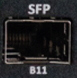
This slot is connected to port B11 and designed to accept an MSA compliant SFP device up to 1Gbps.
3.7. USB Type B
The USB port is an interface used by a host computer for configuration, firmware updates, use with software applications.