2. Introduction and Overview
2.1. Introduction
Thank you for purchasing a RAD-Epsilon XL from Intrepid Control Systems (ICS). The RAD Epsilon XL is an 19-Port Ethernet Managed Switch supporting 100/1000BASE-T1 and 100/1000/10GBASE-T with many AVB/TSN features. Its base functionality is a Layer 2 switch, but it also contains an embedded processor with CAN FD, LIN and a 100Mbps link to the switch. This processor can be used to monitor and transmit messages, and to create hardware simulations for network analysis.
2.1.1. Package Contents
Hardware
The following table summarizes the standard and optional accessories of the RAD-Epsilon XL. Upon receipt, please remove, unwrap and inspect all its contents. If anything is missing or damaged, please contact Intrepid for prompt assistance, using the information at the end of this guide.
USB 2.0 A/B Cable |
1 |
12V Power Supply |
1 |
Optional Purchase |
|
Optional Purchase |
Software
Unless physical media was specifically requested, your box should contain a reference card with instructions on where to download the device drivers and any other purchased software. If your media or reference card cannot be located, please contact Customer Support.
2.2. Device Overview
How does an Ethernet switch work?
If you are unfamiliar with Ethernet switches, this video provides an overview of how Ethernet and Ethernet switches work.
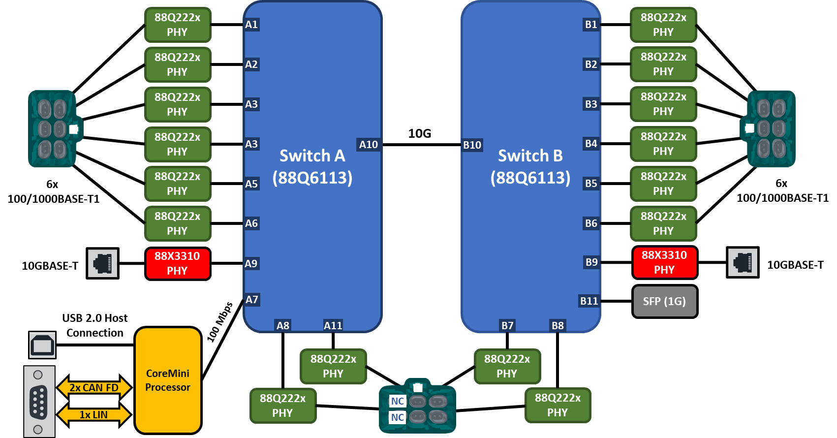
Internally, the RAD-Epsilon XL has two switches. In this document, the switches differentiated with the references of “Switch A” and “Switch B”. Physical port references of the two switches will have the prefixes “A” and “B” respectively. (e.g. A1, B2, etc.)
As can seen below, the switches are bridged between ports A10 and B10. The diagram also indicates the physical media of each port and connector type.
The embedded processor connects over a 100Mbps link to port A7. This processor can be accessed over the USB port by a host computer for real-time communication on its networks or to send scripts that can be executed in standalone mode.
2.2.1. Block Diagram
2.2.2. Hardware Resources
- 2x Marvell 88Q6113 Switches with Embedded AVB/TSN Stack
gPTP (802.1AS-2020)
Credit Based Shaping (Qav)
Time Aware Shaping (Qbv)
Ingress Rate Limiting
TCAM
- 16x 100/1000BASE-T1 Ports (Marvell 88Q222x)
TC10 Automotive Ethernet Sleep/Wake Functionality
Automotive MACsec with Embedded MKA Stack
2x 10GBASE-T Ports
1x 1G SFP Port
- Legacy networks
2x CAN FD
1x LIN
2.2.3. Product Features
Fully-programmable scripting using CoreMini and Vehicle Spy Professional or Enterprise versions
Standalone embedded script execution
USB 2.0 Host Computer Interface
Field Upgradable Firmware
LED indicators for Link Status and Network Activity
Switch and PHY register access for status and configuration
Rugged aluminum enclosure with rubber bumpers for durability
1 Year Limited Warranty
2.2.4. Electrical and Mechanical Characteristics
Device Power: 6-40V
Temperature Range: -40°C to +80°C
Product Dimensions: 6.75” x 8.375” x 1.75
Product Weight: Approx. 2.5 lbs.
H-MTD connection systems for 1000BASE-T1 Ethernet connections
2.3. Product Use Cases
2.3.1. Create a LAN
With the RAD-Epsilon XL, a LAN can be created with up to 16x 100/1000BASE-T1 devices. Additionally, the 10GBASE-T ports allow connecting non-Automotive devices or daisy chaining to another switch.
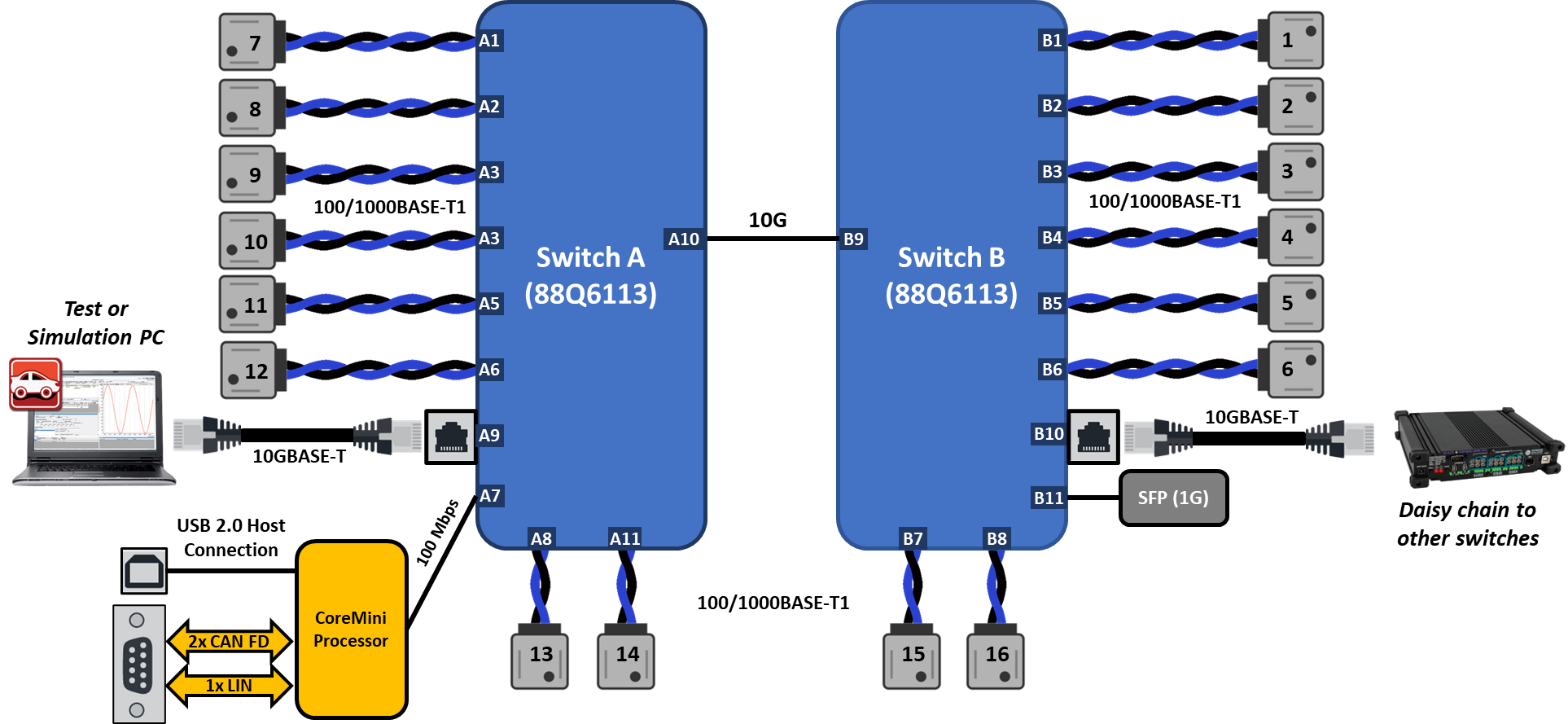
2.3.2. Vehicle Network Interfacing
The primary function of this device is a layer 2 switch, but it can be used as an Ethernet interface through the embedded processor connected to port A7 of the switch. This processor can be used with Intrepid’s Vehicle Spy software or Open Source API to send and receive Ethernet frames on port A7. For more information on how to use Vehicle Spy with this feature, reference Core Features.
Monitoring and Simulating Ethernet Traffic
It is important to understand the distinction that RAD-Epsilon devices are switches and not active taps. Unlike ICS Ethernet tap devices, only a single port of the switch is exposed to Vehicle Spy or your application. Under normal circumstances, the switch will forward frames to ports based destination addresses that it has learned which may or may not yield the desired traffic monitoring or network simulations. Often, the use of port mirroring and/or TCAM is helpful in modifying the switch’s functionality to meet specific use cases.
2.3.3. Simulation and Scripting
The embedded processor can also be used for simulation and scripting. The scripts can run on a host PC as well as compiled to run standalone in the embedded processor using CoreMini. These scripts can be as simple as a periodic message, but Function Blocks can be used to implement arbitrary logic and and state machines useful in specialized test scenarios, ECU simulation, and complex gateways.
2.3.4. PHY and Switch Register Access
Each PHY and switch can be accessed by the embedded processor over MDIO in order to read/write configurations and status registers. More information can be found in Advanced Features
2.4. Hardware Requirements
2.4.1. Device Power Requirements
The RAD-Epsilon XL requires a minimum of 2A at a voltage of 12V. The functional voltage range is from 6V to 40V but will require more current at lower voltages. Using a supply outside of these voltages may make the device malfunction or be permanently damaged.
The RAD-Epsilon XL can be powered by the 2.1mm barrel jack on the front panel. Alternately, power can be supplied using the DB9 on the front panel. Pin assignments for the DB9 can be found this this section,
2.4.2. Computer Interface
Connection to a computer is needed both for configuration of the tool as well as to communicate with the device if you intend to use Vehicle Spy or Intrepid’s available API. The RAD Epsilon XL connects to a host computer using using the USB 2.0 connection on the front panel. As a hardware device, there are no specific requirements on the computer aside from the proper USB interface and the proper device driver installed. Instructions on installing the device driver are covered later with the installation of software.