2. Introduction and Overview
2.1. Introduction
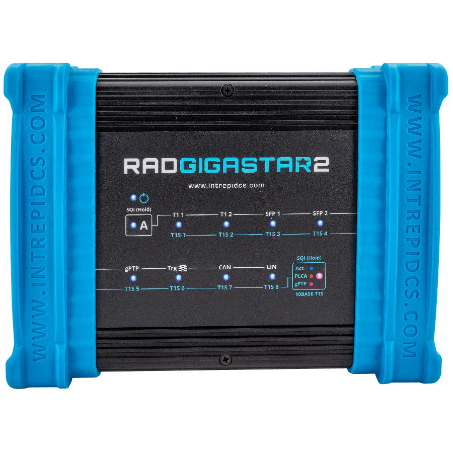
Thank you for purchasing a RAD-Gigastar2 from Intrepid Control Systems (ICS). You will find it a versatile tool for In-Vehicle Networks having 100/1000BASE-T1, 10BASE-T1S, CAN, and LIN.
2.2. Package Contents
Upon receipt, please remove, unwrap and inspect all its contents. If anything is missing or damaged, please contact Intrepid for prompt assistance using the Customer Support information at the end of this guide.
2.2.1. Hardware
Your RAD-Gigastar2 package includes the following:
The RAD-Gigastar2 device
2x 1000BASE-T SFP Modules
2x A standard 8-wire Ethernet cable (CAT5e)
DB-26 Breakout Cable. (DB-25M and DB-9).
A standard USB Type A to Type C SuperSpeed cable
A 12 volt power supply
If purchased, the following accessories may also be present.
2.2.2. Software
If you purchased software with your device, you will receive an email with the software license, a download link for the software, and instruction on installation. If this email cannot be found, please contact Customer Support.
If software was not purchased with hardware, your box should contain a reference card with instructions on where to download the device drivers. If this reference card cannot be located, please contact Customer Support.
2.3. Device Overview
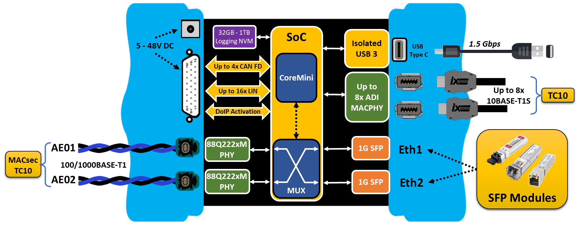
The RAD-Gigastar2 contains a number of different network interfaces and features to allow it to support a wide variety of use cases.
2.3.1. Network Interfaces
The number of available network interfaces on RAD-Gigastar2 depends on which firmware configuration is being used. Either of these configurations can be enabled by changing the firmware using this interface in the configuration utility.
MAX LIN: Maximum number of LIN channels with a reduced count of 10BASE-T1S and CAN ports.
MAX T1S/CAN: A reduced number of LIN channels to enable the maximum number of 10BASE-T1S and CAN ports.
MAX LIN Configuration |
MAX T1S/CAN Configuration |
|
1000BASE-T1 (Marvell 88Q222xM) |
2 |
2 |
1Gbps SFP Ports (1000BASE-X/SGMII) |
2 |
2 |
10BASE-T1S (ADI AD330X) w/ Software selectable internal termination |
6 |
8 |
CAN-FD |
1 |
4 |
LIN /K-Line |
16 (note) |
6 |
DoIP Activation Line |
1 (note) |
1 |
note: Use of DoIP reduces number of LIN channels available.
The use of the DoIP activation line and LIN 15 are mutually exclusive given they share the same connector pin assignment.
2.3.2. Product Features
- Standalone Operation
Embedded script execution
High-performance Gateways
Low-power modes
- Logging Features
Standard 64GB internal NVM (Optional up to 1TB)
400-480 Mbps write speeds
64-bit timestamping with 25 ns accuracy on all Ethernet, CAN and LIN networks
Battery-backed real time clock (RTC)
Axis camera Hosting
Isolated USB 3.0 connection protecting PC from potential damage
Automatic or static master/slave PHY configuration
Software selectable on-board 10BASE-T1S termination (End Node)
LED indicators for Link Status and Network Activity
Field-upgradeable firmware
1 Year Limited Warranty
2.3.3. Electrical and Mechanical Characteristics
Automotive voltage range operation (5V-48V)
Power consumption: ~30W
Temperature range: -40°C to +85°C
Compact design: 7.30” x 5.6” x 1.8”
Rugged aluminum enclosure with rubber bumpers for durability
Light weight: ~1.5 lb. (~0.7 Kg)
H-MTD connection systems for 1000BASE-T1 Ethernet connections
2.4. Operational Overview and Use Cases
The RAD-Gigastar2 has many capabilities and can perform a number of different functions, many of them simultaneously. The Automotive Ethernet ports can be configured as active taps, independent ports, or simply serve as a media converter between dissimilar physical media. At the same time it can also act as an interface to legacy vehicle networks such as CAN FD and LIN.
The following section will outline some of the more common use cases, however it should not be interpreted as a complete list of the device’s full capabilities.
2.4.1. Active Taps
An active tap consists of a pair of Ethernet ports interposed between two Automotive Ethernet devices to monitor network traffic between them. The figure below shows traffic between two ECUs. Each Messages received by the tap is immediately forwarded to the other ECU, but a copy of the message is also encapsulated with a precision timestamp before it is sent to a host computer or data logger. The mode of operation shown below is known as “Cut-Through” because the frames are forwarded with minimal latency. (They “Cut-Through” the active tap)
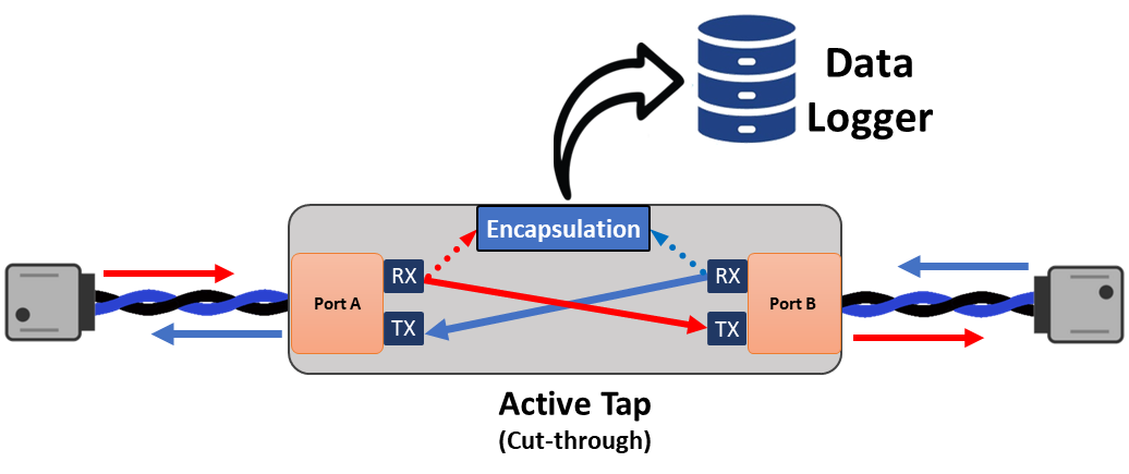
Intrepid’s active taps can also inject messages into the communication between the devices. This requires the tap to operate in a “Store and Forward” mode. This means that the frames are received in their entirety and placed in a transmit buffer until they can injected between frames being sent between the two devices.
Store and Forward Latency
Store-and-Forward switching introduces latency between devices, which varies depending on the frame size. In most cases, this latency does not significantly impact system performance. However, when gPTP is used, it contributes to the overall link delay between devices. Depending on the gPTP configuration, this additional delay may interfere with proper operation.

The RAD-Gigastar2 contains 2x 100/1000BASE-T1 PHYs and 2x SFP ports that can be configured as independent ports or up to two 1Gbps active taps.
Aggregate Bandwidth
This device has network interfaces that support an aggregate bandwidth of over 8Gbps. However, the connection to the host computer is limited to either USB 3.0 or a single 1000BASE-T SFP port and can become a bottleneck.
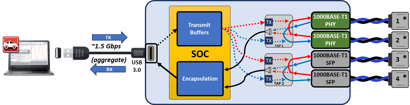
Single 100/1000BASE-T1 Active Tap
In this mode, the RAD-Gigastar2 serves as a “man-in-the-middle” sending timestamped copies of frames between the two devices to the host computer running either Vehicle Spy or an application using Intrepid’s Open Source API .
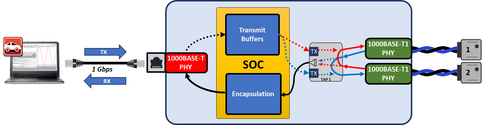
In this configuration, the RAD-Gigastar2 is connected to a host computer using USB 3.0 or either of the SFP ports and one of the provided 1000BASE-T SFP modules. This interface is full-duplex, meaning that in addition to using the PC to monitor messages sent by the Automotive Ethernet nodes attached to it, you can create and send custom messages from the PC to the nodes as well. This allows you to query, test, configure and manage these nodes using Vehicle Spy or applications using Intrepid’s Open Source API
Low Latency Tapping
The default configuration of RAD-Gigastar2’s active tap is “store & forward” mode. This introduces some latency because the entire frame must be received on one port before it is forwarded to the other. There is also a “low latency” mode, however this prohibits the ability to inject messages into the communication between ECUs using Vehicle Spy software.
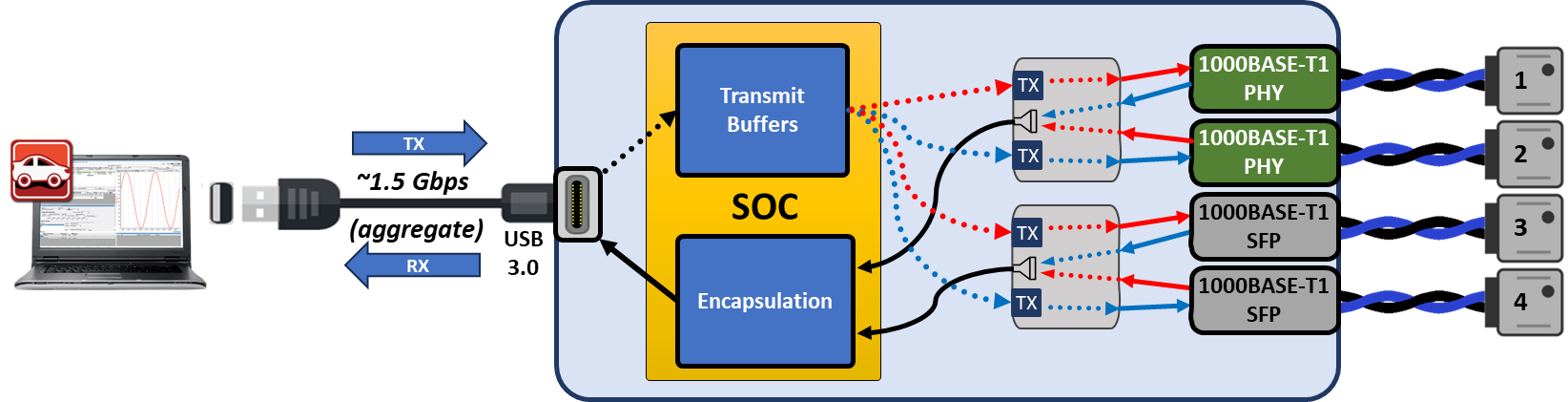
Dual 100/1000BASE-T1 Active Taps
The SFP ports can be used as a second active tap. In this configuration, the connection to the host computer must use the USB 3.0 port.
Mixed Media Active Tap
The SFP ports can be paired with the internal BASE-T1 PHYs to create active taps between devices using different physical media.
10BASE-T1S Active Taps
Two 10BASE-T1S ports (AE03/AE04) can also be paired with the internal PHYs or SFP ports, allowing up to 3 taps.
2.4.2. Independent Ports
Instead of being placed between Automotive Ethernet devices, the RAD-Gigastar2 can be configured such that each port is an independent communication channel between the host computer and devices connected to each port. In this mode, each port can be used independently to transmit and receive messages using VSPY, Intrepid’s open source APIs, or Network Adapter Server. This is often used to test multiple ECUs in parallel as well as “Gang Flash” a large number of ECUs at the same time.
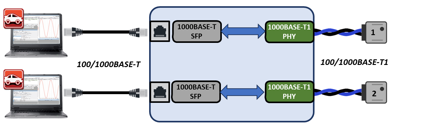
2.4.3. Media Conversion
There is no host PC in this configuration, but the RAD-Gigastar2 is simply converting 100/1000BASe-T1 to whatever media is provided by the SFP modules present in the SFP ports.
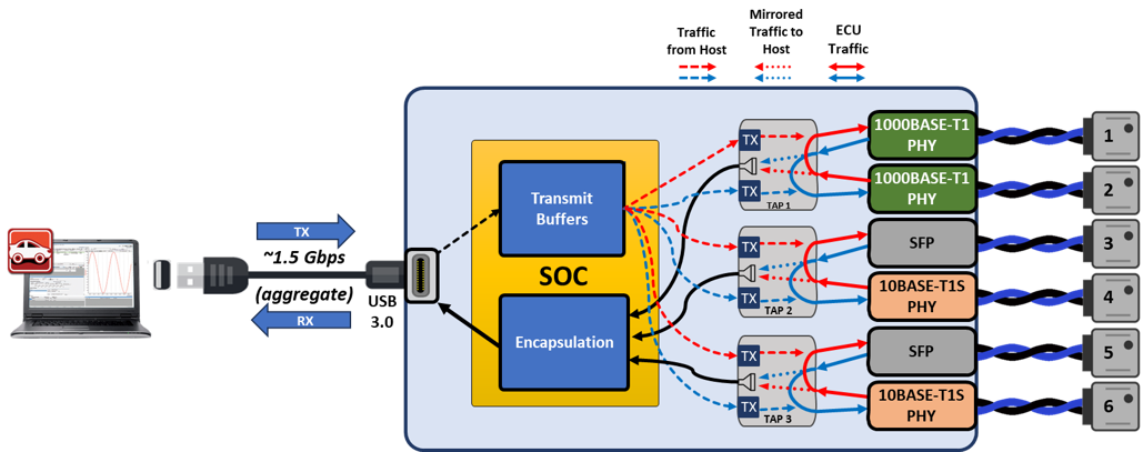
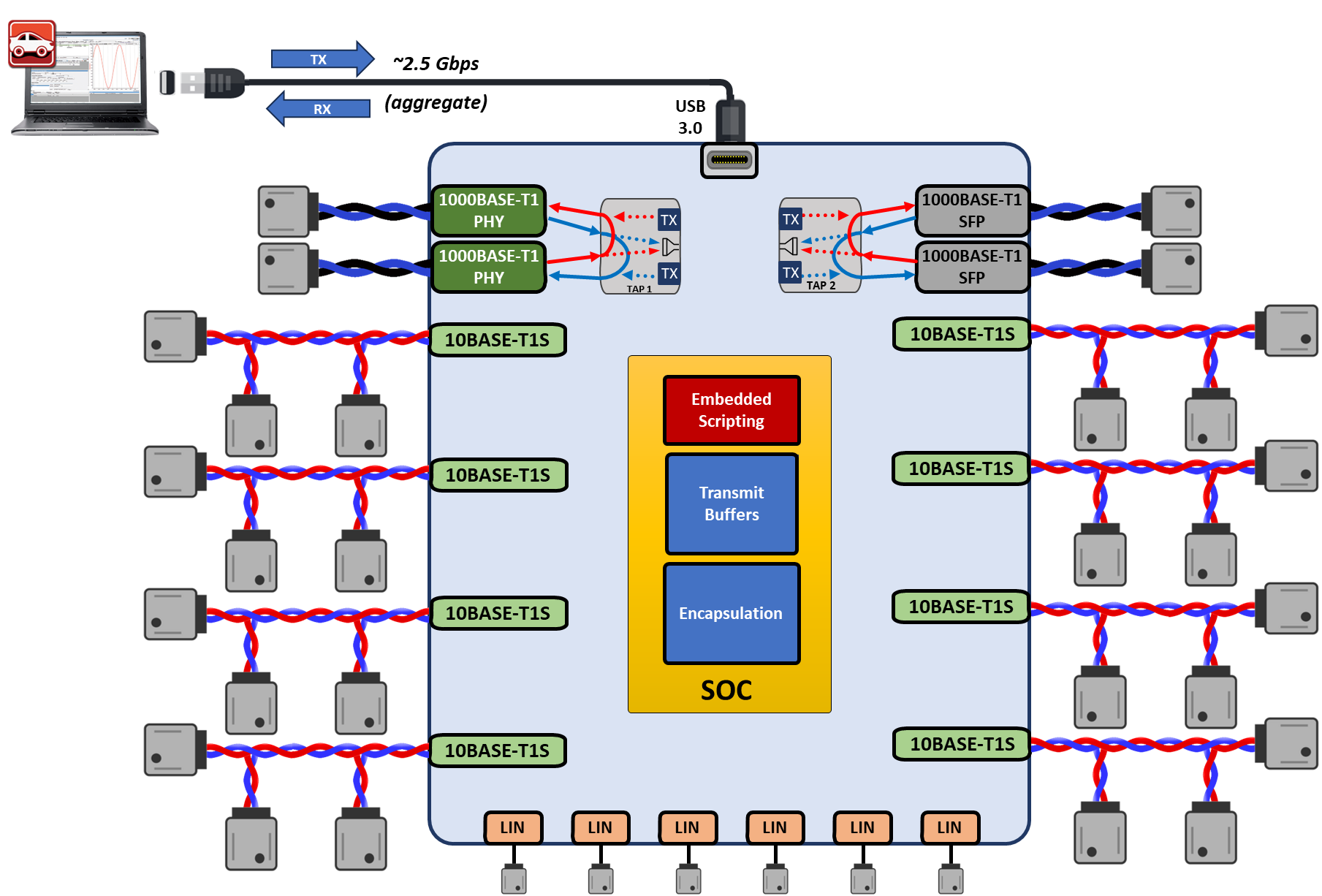
2.4.4. Complete Zonal Test Solution
Zonal Vehicle Architectures consist of a number of different networks of different physical media, speeds, and protocols. The RAD-Gigastar2 was designed specifically for these architectures by having all of these networks integrated into a single device. The following diagram shows how the RAD-Gigastar2 could be used to instrument an entire zone of the vehicle as well as simulate applications and functions of the vehicle associated with the connected devices. (CAN FD is not shown in this diagram, but 4 ports exist to accommodate architectures that have not fully adopted Ethernet)
2.4.5. Simulation and Scripting
Using Vehicle Spy, messages can be created to be transmitted on any network with custom data. These messages can be sent manually or on a user defined schedule. Additionally, scripts can be easily written to implement logical state machines capable of sending these messages based on timers, events, and state variables. Common uses of these scripts are generating test sequences, simulating ECUs, and implementing network gateways. A very powerful feature of most Intrepid products is that these scripts can be compiled and sent to the hardware’s embedded processor to function as a standalone device. This is explained in more detail in the CoreMini section of this guide.
2.4.6. PHY Register access
In any mode, each PHY can be accessed by the device’s embedded processor in order to read and write configurations registers. More information can be found in Device Register Access
2.5. Hardware Requirements
2.5.1. Device Power
The RAD-Gigastar2 requires a DC supply between 5V-48V that provides 30 watts or more. It draws a nominal current of 2A at 12V.
Power can supplied either by the barrel jack or through the DB-26 connector. See Device Power, SFPs, and CAN/LIN interfaces for specific pin assignments.
2.5.2. Computer Interface
Connection to a computer is needed both for configuration of the tool as well as to communicate with the device if you intend to use Vehicle Spy or Intrepid’s Open Source API .
As a hardware device, there are no specific requirements on the computer aside from the proper interface and the proper device driver installed. There are 2 ways to connect the RAD-Gigastar2 to a host computer.
SFP Port (typically 1000BASE-T)
Either SFP port can be used to connect the RAD-Gigastar2 to a host computer through a 1000BASE-T Ethernet Adapter. No specific drivers are required.
IT Policies
With IT security a growing concern, many IT departments block certain types of Ethernet traffic and communication. In some cases, this has been found to interfere with Intrepid devices connected to a host computer using Ethernet. If you find you are having trouble please contact our Customer Support.
USB 3.0 (Type C Connector)
This port can be used to connect RAD-Gigastar2 to a host PC instead of using one of the SFP ports. A slow connection is sufficient to configure the device. But to take full advantage of Gigabit speeds, it is important to connect to a certified USB 3.0 port using a USB 3.0 cable certified for SuperSpeed. Using inferior hardware and cables may result in erratic performance.