3. A Tour of Gigastar2 Hardware
Before learning how to configure and set up the device, let’s examine the device from all sides to understand all of its interfaces and status indicators.
3.1. Label and Status Indicators
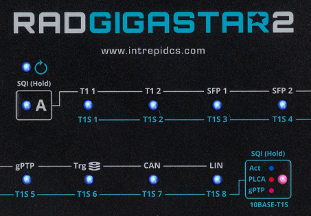
The RAD-Gigastar2 has two membrane buttons,  and
and 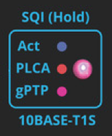 .
Pressing one button will activate the LED inside it and
deactivate the other button’s LED.
.
Pressing one button will activate the LED inside it and
deactivate the other button’s LED.
3.1.1. The Button
Device Status
When this button is active, the color of it’s LED indicates the following.
LED Behavior |
Status |
|
Device Powered |
|
Online with Vehicle Spy (Ethernet) |
|
Online with Vehicle Spy (TCP) |
|
Online with Vehicle Spy (USB) |
Network/gPTP/Logging Status
Notice that the white outline of this button intersects with a white line that connects the white text above the other status LEDs. This is to denote that when this button is active, the other LEDs show information related to the white labels above them.
Label |
Network or Function |
LED Behavior |
|
T1 1 |
AE01 (1000BASE-T1) |
|
|
T1 2 |
AE02 (1000BASE-T1) |
||
SFP 1 |
Ethernet |
||
SFP 2 |
Ethernet 02 |
||
CAN |
CAN1-4 (Logical OR of all CAN Buses) |
||
LIN |
LIN1-6 (Logical OR of all LIN Buses) |
||
gPTP |
gPTP status |
|
gPTP Leader |
|
gPTP Follower (locked) |
||
|
gPTP Follower (not locked) |
||
|
Error |
||
|
gPTP disabled |
||
|
Logging Activity |
|
NVM Write |
|
NVM Read |
||
|
NVM Error |
||
|
Trigger Collection Active |
||

3.1.2. The Button
Notice the blue outline of this button intersects with a blue line that connects the blue text below the LEDs. This is to denote that when this button is active, the LEDs display information related to the blue labels below them. (The 10BASE-T1S Networks 1-8)
The color of the LED within this button indicates which information is displayed for the 10BASE-T1S networks.
|
LED Behavior |
Port Status |
|
|
Frame Transmitted |
|
Frame Received |
|
|
Error (e.g. Bad CRC, PLCA error) |
|
|
Port Disabled |
|
|
|
BEACON present |
|
Collision |
|
|
Jabber |
|
|
Unexpected BEACON |
|
|
Empty Cycle |
|
|
CSMA/CD Mode |
|
|
Port Disabled |
|
|
|
Disabled |
|
Leader |
|
|
Follower/Locked |
|
|
Follower/Not Locked |
|
|
Error |
Signal Quality Index (SQI)
Momentarily holding will display SQI information for 100/1000BASE-T1 networks,
and holding will display the SQI of the 10BASE-T1S networks.
The color of the LED can be interpreted as follows.
LED Color |
SQI |
Bit Error Ratio |
|
T1S |
T1 |
||
|
0 |
0 |
BER > 10e-10 |
1 |
|||
2 |
|||
|
1 |
3 |
BER < 10e-10 |
4 |
|||
|
2 |
5 |
|
6 |
|||
7 |
|||
3.2. Connector Interfaces
3.2.1. Device Power, SFPs, and CAN/LIN interfaces
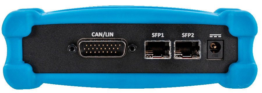
DB-26 Connector: CAN/LIN
In addition containing an alternate power connection, the CAN, LIN, and DoIP interfaces are located in this connector. The pin assignments are listed below and can also be seen on the bottom label of the device.
Mutually Exclusive Networks
The RAD-Gigastar2 features two different firmware configurations based on which networks are needed for an application. The use of some networks are mutually exclusive between these two configurations. The chart below shows the pin assignments for each port and their availability in a given firmware configuration.
Pin |
Signal |
||
MAX LIN Config |
MAX CAN/T1S Config |
||
1 |
LIN 01 |
LIN 01 |
|
2 |
|
DW CAN 04 L |
|
3 |
LIN 03 |
LIN 03 |
|
4 |
DW CAN 01 L |
DW CAN 01 L |
|
5 |
LIN 05 |
LIN 05 |
|
6 |
|
DW CAN 02 L |
|
7 |
|
DW CAN 03 L |
|
8 |
LIN 07 |
|
|
9 |
LIN 09 |
|
|
10 |
GND |
GND |
|
11 |
LIN 02 |
LIN 02 |
|
12 |
|
DW CAN 04 H |
|
13 |
LIN 04 |
|
|
14 |
DW CAN 01 H |
DW CAN 01 H |
|
15 |
LIN 06 |
|
|
16 |
|
DW CAN 02 H |
|
17 |
|
DW CAN 03 H |
|
18 |
LIN 08 |
|
|
19 |
VBAT |
VBAT |
|
20 |
LIN 10 |
|
|
21 |
LIN 11 |
|
|
22 |
LIN 12 |
|
|
23 |
LIN 13 |
|
|
24 |
LIN 14 |
|
|
25 |
LIN 15/ DoIP Activation |
LIN 15/ DoIP Activation |
|
26 |
LIN 16 |
|
|
SFP Ports
The RAD-Gigastar2 ships with two 1000BASE-T SFP modules which can be used in the sockets SFP1 and SFP2. 100/1000BASE-T1 and Optical SFP modules are also available for purchase.
SFP Compatibility
While there are many types and many suppliers of SFP modules, it is important to use hardware that has been fully verified by ICS to insure full compatibility and reliable performance.
ICS Approved SFP Modules
Media |
Manufacturer |
Part Number |
100/1000BASE-T1 |
Intrepid |
|
10/100/1000BASE-T (Copper) |
Finisar |
FCLF8522P2BTL |
FS |
SFP-GB-GE-T |
|
1000BASE-SX (Optical) |
Finisar |
FTLF8519P3BTL |
FS |
SFP1G-SX-85 |
Configuring Intrepid’s 10BASE-T1S and MultiGBASE-T1 SFPs
Intrepid’s 10BASE-T1S and MultiGBASE-T1 SFPs are not compatible with the RAD-Gigastar2 however, they can be configured using the RAD-Gigastar2 for use in another host.
Barrel Jack: 5-48V (Right):
The device can be powered with this barrel jack using the DC supply provided with your purchase. If an alternate DC supply is used, it must be within the range of 5V-48V with a current capacity of 2 Amps, or the device may malfunction or be permanently damaged.
3.2.2. 100/1000BASE-T1, 10BASE-T1S, and USB Interfaces
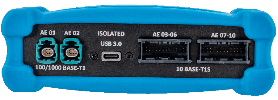
H-MTD Connectors: 100/1000BASE-T1 (AE01 / AE02)
The H-MTD connectors on the left are connected to the 100/1000BASE-T1 ports, AE 01 and AE 02.
H-MTD Connector Pinout |
||
Pin # |
Label |
Description |
1 |
TRD+ |
Data transmit and receive, positive |
2 |
TRD- |
Data transmit and receive, negative |
Isolated USB 3.0 (Type C Connector)
This USB port is electrically isolated to protect it and a host computer from potential damage. It functions identically to connecting the RAD-Gigastar2 to a computer using one of the SFP ports. It has the advantage of supporting transfer speeds higher than 1Gbps, as well as allows the use of the SFP ports in a second active tap configuration.
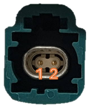
NanoMQS Connectors: 10BASE-T1S (AE03 - AE10)
Each 10BASE-T1S port has two sets of pins on the NanoMQS connectors to minimize stub length by connecting the RAD-Gigastar2 to a mixing segment in an “In/Out” configuration.
A NanoMQS plug and pin kit is shipped with the RAD-Gigastar2, however additional kits can be purchased here
The same components are also available from many electronic component distributors
NanoMQS Crimp Contacts 2-2112449-1
NanoMQS Plugs 2177558-1
AE03 - AE06 Pin Assignments
In |
Out |
|
AE 03 P |
1 |
20 |
AE 03 N |
2 |
19 |
AE 04 P |
3 |
18 |
AE 04 N |
4 |
17 |
AE 05 P |
5 |
12 |
AE 05 N |
6 |
11 |
AE 06 P |
7 |
10 |
AE 06 N |
8 |
9 |
NC |
13-16 |
|
AE07 - AE10
In |
Out |
|
AE 07 P |
1 |
20 |
AE 07 N |
2 |
19 |
AE 08 P |
3 |
18 |
AE 08 P |
4 |
17 |
AE 09 P |
5 |
12 |
AE 09 N |
6 |
11 |
AE 10 P |
7 |
10 |
AE 10 N |
8 |
9 |
NC |
13-16 |
|
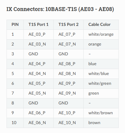
Pre-production IX Connector Pinout
In pre-production units, IX connectors were used for the 10BASE-T1S ports. a chart with this pinout can be
found here