5. A Tour of neoVI Hardware
Let’s now take a short tour of the neoVI’s hardware. We’ll examine the device from all sides, showing its external components and explaining what each does. This will help you become more familiar with the unit so you can more easily set up, configure and use it.
Like many Intrepid products, the neoVI FIRE 3, neoVI RED 2 and neoECU 22 is designed so that all of its connectors are located on its sides, making the device easier to use in cramped quarters. We’ll refer to these as the left side and right side of the unit, as oriented when facing the device with its top label text readable.
Warning
The neoVI’s is a complex device that does not contain any user-serviceable parts. Do not attempt to open the case of the neoVI FIRE 3, neoVI RED 2 and neoECU 22 unless specifically instructed to do so by an Intrepid Control Systems technician, or you risk possible injury or damage to the unit.
5.1. Case and Overall Design
The neoVI’s device (neoVI FIRE 3, neoVI RED 2 and neoECU 22 ) is enclosed in a sturdy black-anodized metal case. The device has been designed and tested for in-vehicle use, and is operational in a temperature range from -40°C to +85°C. An overall view of the neoVI’s device can be seen in Figure 3.
Connectors and ports are often a point of failure with hardware devices. To ensure that the neoVI’s provides you with years of reliable service, Intrepid has ruggedized the physical interfaces on the device by using reinforced metal connectors.
To further protect the device against bumps and drops, it has red-colored rubber bumpers on both ends. These bumpers are removable, but there is no need to do this under normal circumstances, and we recommend that you leave them in place.
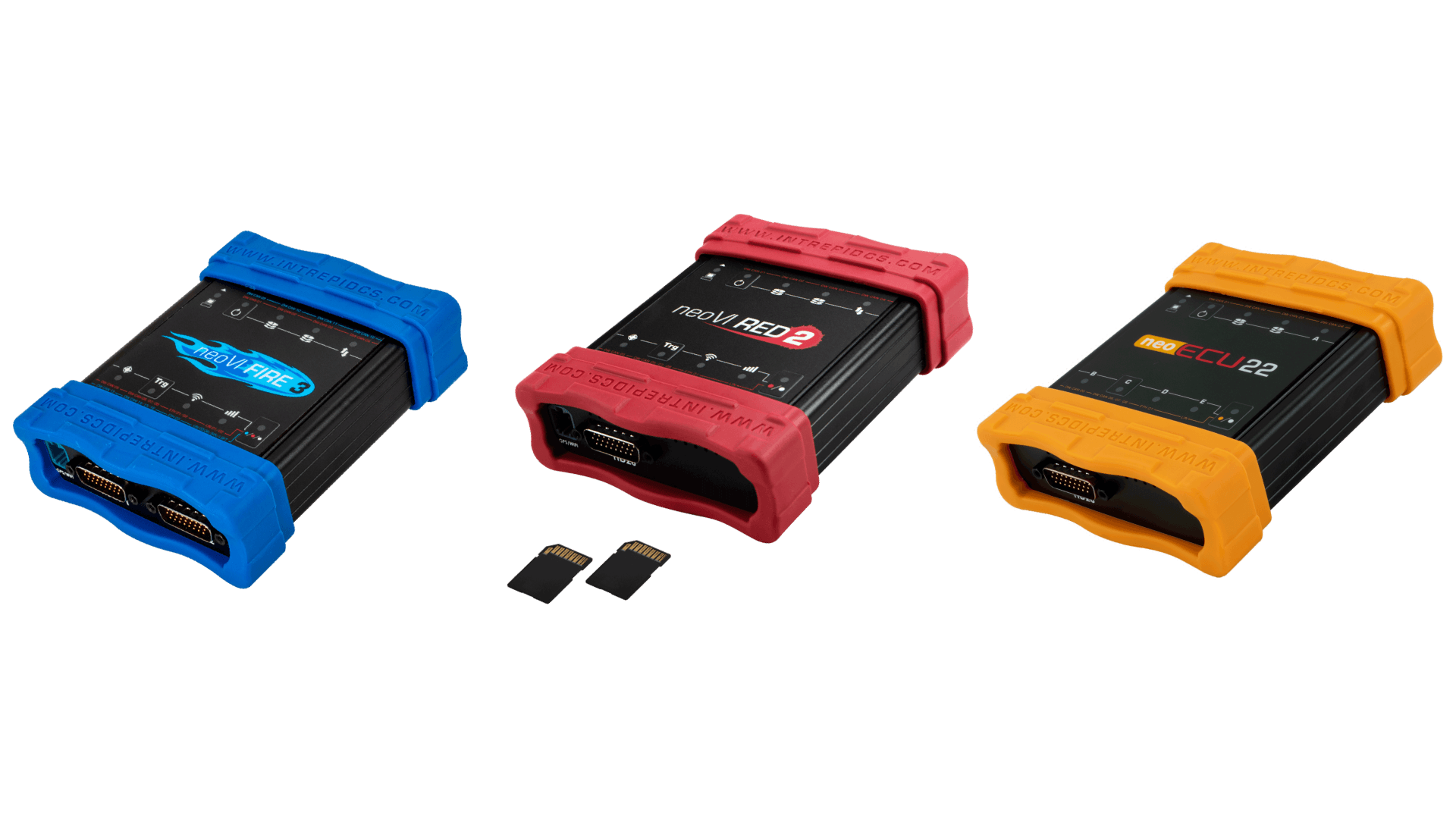
Figure 3: Overview of the neoVI’s device (neoVI FIRE 3, neoVI RED 2 and neoECU 22)
The bottom of the neoVI’s device contains useful reference information, including the device serial number, pinouts of its DB-26 and Antenna information (Figure 4). Pinouts for all neoVI’s connectors and cables can be found in Chapter 8.
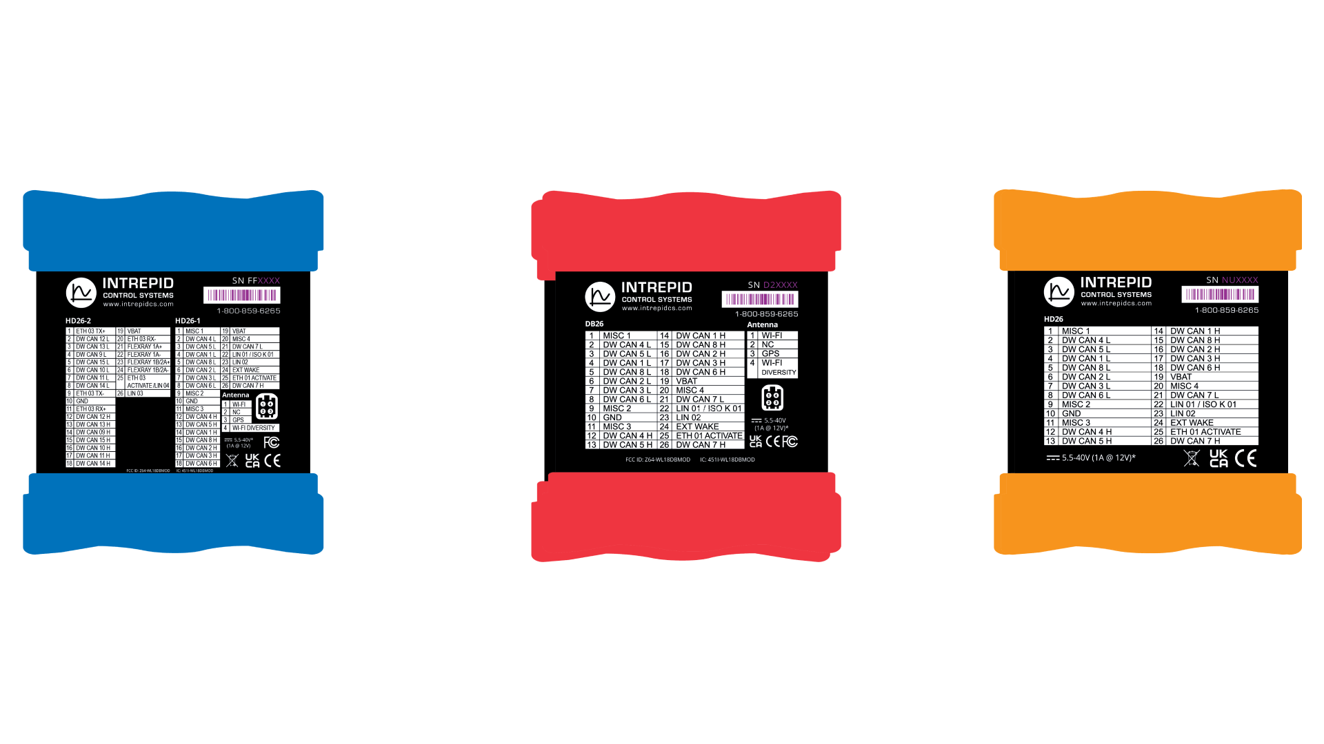
Figure 4: neoVI’s devices Bottom View
5.2. Left Side Interfaces and Connectors
The left side of the neoVI RED 2 contains two components: the GPS/WiFi Connector and HD-26 connector while neoECU 22 has 1 Barrel Jack & 2 GB Ethernet Connectors, 2 full size SD cards (Figure 5).
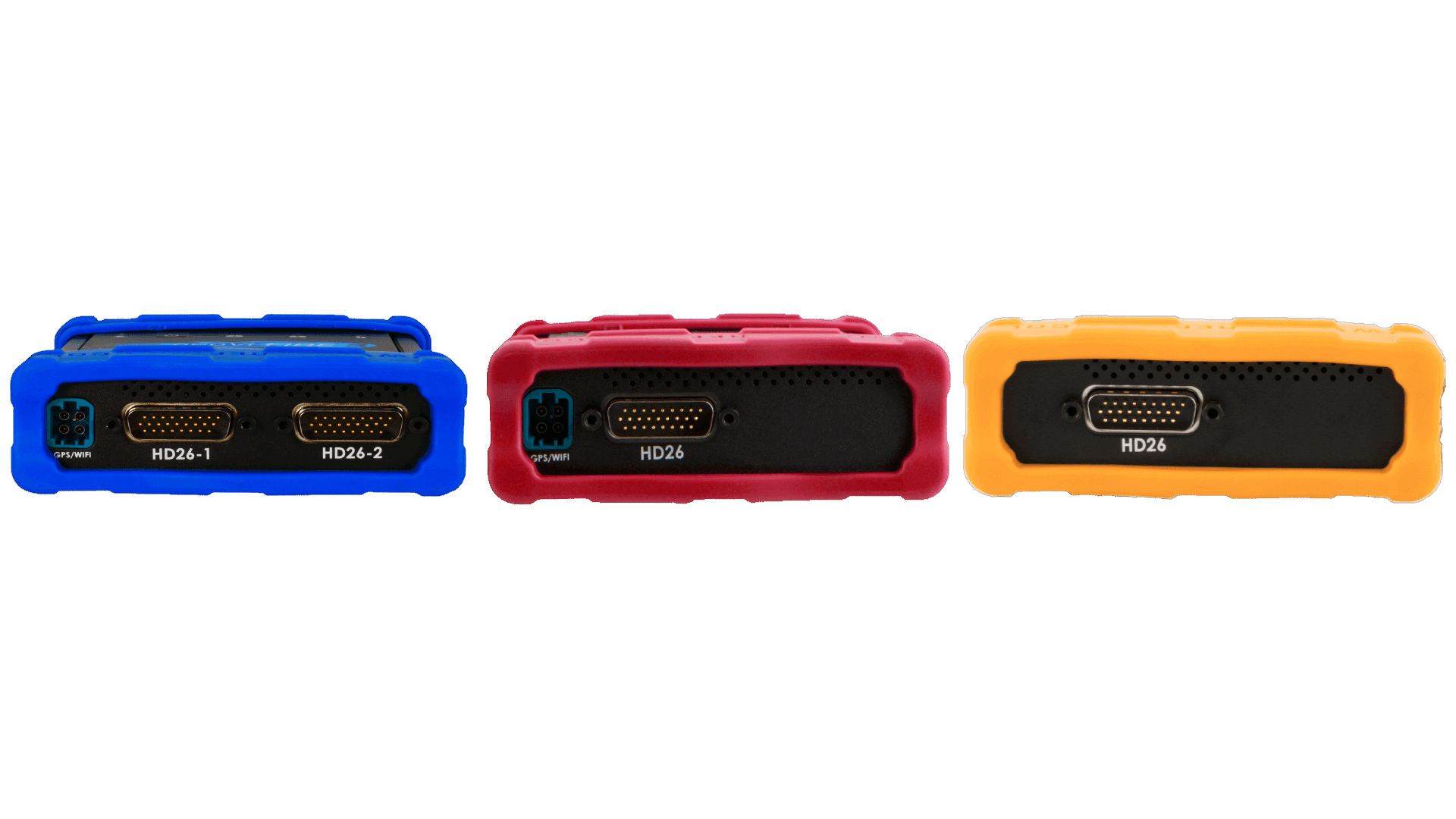
Figure 5: neoVI RED 2 Left Side View.
5.2.1. GPS/WiFi Connector
WIFI Antenna with 4-position MateAX connector (Red 2/Fire 3) allows you to connect RAD-4G data modem to add wireless 4G support to your compatible neoVI products.
GPS/WiFi Connector
5.2.2. HD-26 Network Interface Connector
This male, high-density, 26-pin D-subminiature connector is the primary means by which the neoVI’s interfaces with vehicle networks. One of two network interface cables is connected to this port, enabling CAN, LIN and Ethernet messages to be passed between the network and device. This connector also provides primary power to the device.
5.3. Right Side Interfaces and Connectors
This side of the neoVI’s device contains most of its connectors, ports and slots (Figure 6).
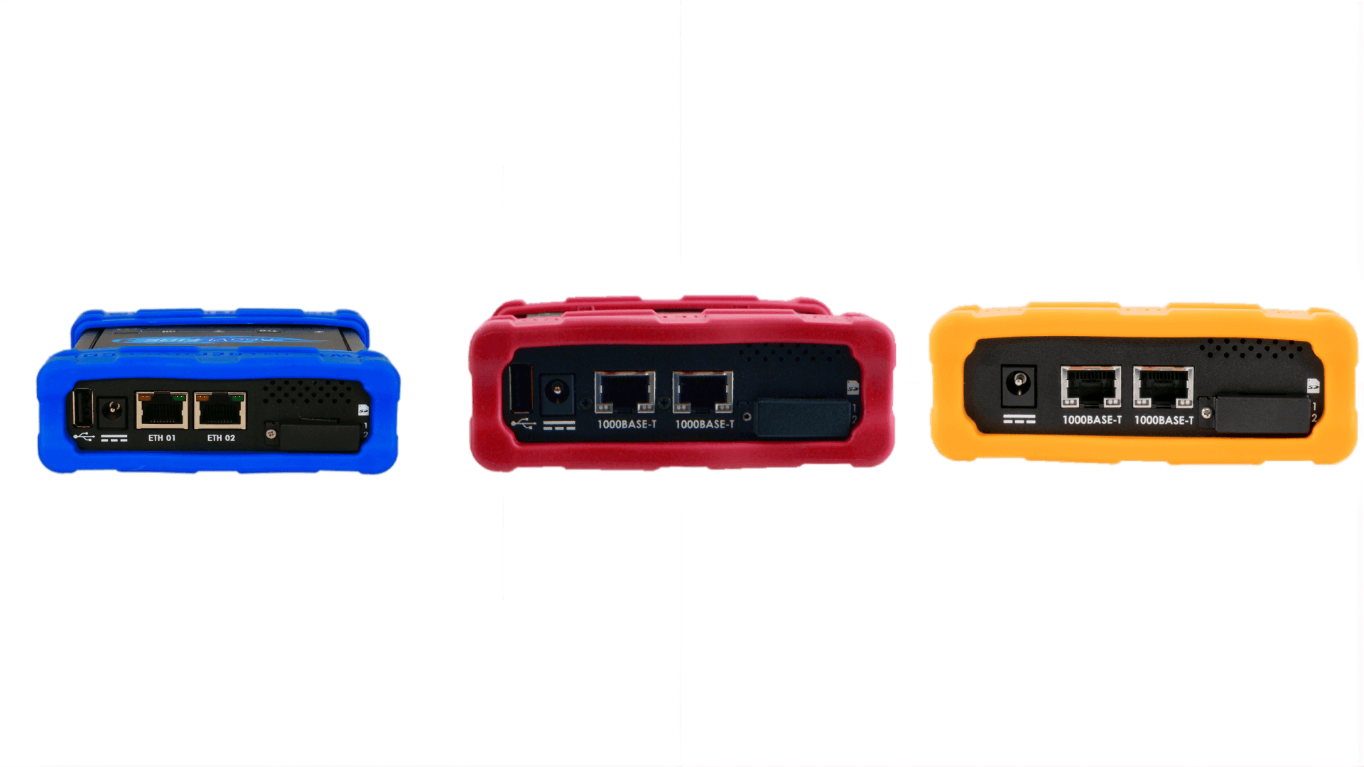
Figure 6: neoVI’s device (neoVI FIRE 3, neoVI RED 2 and neoECU 22) Right Side View
5.3.1. USB Host Port
The USB “A” connector allows the neoVI FIRE 3 and neoVI RED 2 to act as a USB host, so other devices can plug into it. Please see Section 7.2 for more details.
Note - neoECU22 doesn’t comes with USB “A”.
5.3.2. Barrel Jack
The device can be powered with this barrel jack using the DC supply provided with your purchase. If an alternate DC supply is used, it must be within the range of 5V-60V with a current capacity of 1 Amp, or the device may malfunction or be permanently damaged.
5.3.3. 1000BASE-T / RJ-45 Port: An industry-standard conventional Ethernet device.
Link LED (Green): Indicates that a valid link has been established between your device and another 10/100/1000 Ethernet device.
Activity LED (Orange): Flashes when traffic passes in either direction over the attached Ethernet cable.
In normal operation you should see the Link LED always on, and the Activity LED flashing at a variable rate, with faster flashing meaning that more data is being transferred.
5.3.4. Full Size SD Slot and Cover
This slot holds the two full size cards that store captured or logged data by the neoVI FIRE 3, neoVI RED 2 and neoECU 22. It is protected by a metal cover that prevents accidental ejection of the card and protects the slot from dirt and debris.
You can download the contents of the installed SD card over Ethernet, or for larger data sets, remove the card and use the provided external card reader.
5.4. neoVI FIRE 3 COMPUTE Interfaces
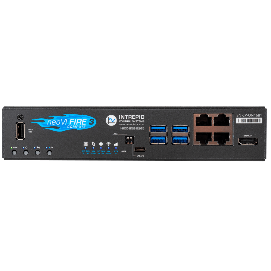
Figure 20: neoVI FIRE 3 COMPUTE Front View.
5.4.1. Front Panel Interfaces and Connectors (Left to Right):
FIRE 3 USB (USB Type-A): A dedicated accessory port used to connect Intrepid hardware accessories, such as the RAD-IO2 thermocouple interface or the neoVI MIC2 manual trigger button.
Programmable Buttons: Four user-programmable buttons that can be scripted to trigger specific events, such as marking a data log or activating a function during a test drive.
Status LEDs: A bank of 10 programmable tri-color LEDs that provide immediate visual feedback on link status, error frames, and network activity.
Night Mode Switch: A DIP switch located below the LEDs that allows users to instantly turn off the front panel lights to prevent driver distraction during night testing.
UPDATE Port (USB-C): A configuration port typically used for firmware updates or direct device communication.
RPi USB 3.0 Ports (x4): Four high-speed USB 3.0 ports connected directly to the internal Raspberry Pi Compute Module. These are used for “Edge” peripherals such as cameras for video logging, external USB storage, or other USB sensors, keyboards or mouse.
DISPLAY Port: A video output connected to the internal Raspberry Pi, allowing you to connect a monitor for a full desktop Linux interface or debugging “Headless” scripts locally.
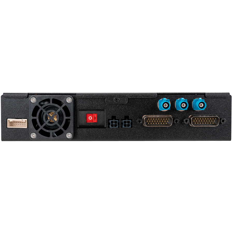
Figure 21: neoVI FIRE 3 COMPUTE Back View.
5.4.2. Back Panel Interfaces and Connectors (Left to Right):
MISC I/O: A connector for General Purpose I/O (GPIO from RPi) and MISC IO from neoVI FIRE 3, allowing for integration with external analog/digital sensors or triggers.
Power Switch: A master rocker switch to power the device on or off.
RAD-4G Power: A dedicated 4-pin power output designed to power an external RAD-4G modem for cellular connectivity.
Main Power Input: The primary power input for the device, supporting a wide automotive voltage range of 5-60V.
DB26-1 Connector: The primary HD26 connector carrying the first set of vehicle network channels (CAN FD, LIN, etc.).
Wi-Fi 1 & 2 (FAKRA): Two Blue FAKRA connectors for attaching external Wi-Fi antennas (supporting diversity) to boost the range of the internal 802.11a/b/g/n Wi-Fi.
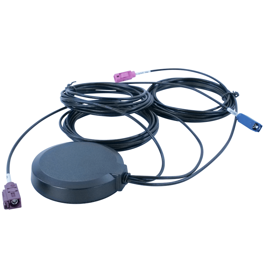
GPS (FAKRA): A Blue FAKRA connector for attaching an external high-precision GPS antenna for location tracking and time synchronization.
DB26-2 Connector: The secondary HD26 connector carrying the remaining vehicle network channels.
5.5. Membrane LED Display and Keypad
The neoVI features a membrane with 10 LEDs that provide instant visual feedback on the device’s status and two keypad buttons for toggling indicator modes and other functions. Both the LEDs and buttons are scriptable, allowing for user input via the buttons and customizable information display through a CoreMini program running on the neoVI.
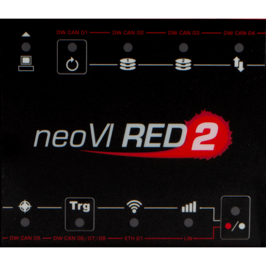
Figure 7: neoVI RED 2 Membrane LED Display and Keypad
5.5.2. Network/Logger Status RGB LEDs
The membrane features 8 RGB (full-color) LEDs arranged in two on the device. The interpretation of each LED’s meaning depends on whether the top-left (CoreMini icon) button or the bottom-right (red and white dot) button has been pressed. This allows the 8 LEDs to indicate a total of 16 different status conditions.
To understand an LED’s current meaning:
Identify which button’s LEDs (CoreMini icon or red and white dot) are flashing, indicating the active set.
Refer to the corresponding color label (red or white) to interpret the indicated status.
5.5.3. Interpretation of RGB LED Colors
These “RGB” LEDs contain separate red, green, and blue elements. For network indicators, each color signifies a different aspect of the device’s overall status:
Green: Device is transmitting messages on this channel.
Blue: Device is receiving messages on this channel.
Red: Device is detecting errors on this channel.
Multiple LED components can be lit simultaneously, producing the following mixed colors:
Green + Blue (Cyan): Device is transmitting and receiving on this channel.
Green + Red (Yellow): Device is transmitting and detecting errors on this channel.
Blue + Red (Magenta): Device is receiving and detecting errors on this channel.
Green + Blue + Red (White): Device is transmitting, receiving, and detecting errors on this channel.
The intensity of these LEDs is proportional to the amount of traffic on the corresponding network. Slower traffic results in a dimmer flash, while heavy traffic produces a brighter LED. The blink rate remains constant regardless of traffic level.
5.5.4. Dedicated Status LEDs
In addition to the RGB network/logger status LEDs, several other LEDs provide specific device status information:
General Status LED
Blink Orange : Device is Powered
Blink White : Host Commmunication Activity
Blink Blue/Green : Device is Online
Blink Magenta: Script is Running
5.5.5. Script Status LED
Blink Red: Device is running a script
5.5.6. SD Card Status (x2)
Blinks Green: Indicates any SD Card erase/write access.
Blinks Blue: Indicates any SD Card read access.
5.5.7. Upload Status LEDs
Blink white if a connected Wireless neoVI client indicates pending uploads.
5.5.8. GPS Status LEDs
Blinks Blue: When receiving GPS sentences.
Solid Green: If there is a valid GPS lock.
5.5.9. Trigger Status LEDs
Blink white if there are any collections currently collecting post-trigger data
5.5.10. WiFi Status LEDs
Indicates the state of the Linux WPA supplicant:
Cyan - WPA_DISCONNECTED
Magenta - WPA_INTERFACE_DISABLED
Blue - WPA_SCANNING
Orange - WPA_AUTHENTICATING / WPA_ASSOCIATING / WPA_ASSOCIATED / WPA_4WAY_HANDSHAKE / WPA_GROUP_HANDSHAKE
Yellow - WPA_COMPLETED
White - WPA_UNKNOWN
Green - User Control / Unused
5.5.11. Cellular Status LEDs
Solid Red: As of version 3.9.10.9, always indicates cellular connectivity status.
Figure 8 shows a photograph of the top membrane of a neoVI’s in active use, with the blue set of status indicators active, meaning that transmissions are occurring on fie channels and errors on one.
As a further cue to network activity, the intensity of these LEDs is proportional to the amount of traffic on the corresponding network. Slower traffic on a network will cause the network’s LED to flash more dimly, while heavy traffic will cause the LED to be brighter. Note that the blink rate remains the same regardless of traffic level.
Figure 8: neoVI RED 2 Membrane LED Display and Keypad Showing Active LEDs. In this image, the blue set of LED meanings is active, as indicated by the green LED being lit within the blue computer icon in the top left corner (this LED alternates between green and red when the device is online). The other LEDs thus mean that the neoVI RED 2 is active and transmitting on the DW CAN1, DW CAN2, DW CAN3, DW CAN4 and DW CAN5 channels (in use these all flash a few times per second.) Note that the LED for DW CAN4 is actually yellowish; it is flashing both a bright green and a dim red to indicate errors while transmitting on the DW CAN4 channel**
5.5.12. “RED Set” LED Status Indicators
When the Red Button (bottom-right keypad button) is pressed and its LEDs are flashing, the 8 RGB LEDs correspond to the red labels on the neoVI membrane. The LEDs are listed from top to bottom, then left to right, as viewed on the device.
Label |
Description |
|---|---|
DW CAN 01 |
Transmit / receive / error status of DW CAN channel 1 |
DW CAN 02 |
Transmit / receive / error status of DW CAN channel 2 |
DW CAN 03 |
Transmit / receive / error status of DW CAN channel 3 |
DW CAN 04 |
Transmit / receive / error status of DW CAN channel 4 |
DW CAN 05 |
Transmit / receive / error status of DW CAN channel 5 |
DW CAN 06/07/08 |
Transmit / receive / error status of DW CAN channel 6, 7, 8 |
TRG |
Trigger Membrane Button to control trigger data logger depending on CAN mode selected (see Section 5.5) |
DoIP |
Transmit / receive / error status of Ethernet channel depending on CAN mode selected (see Section 5.5) |
LINS |
Status of all LIN channels depending on CAN mode selected (see Section 5.5) |
5.5.13. “White Set” LED Status Indicators
When the White Button (bottom-right keypad button) is pressed and its LEDs are flashing, the 8 RGB LEDs correspond to the white labels/icons on the neoVI membrane. The LEDs are listed from top to bottom, then left to right, as viewed on the device.
Label/Icon |
Description |
|---|---|
|
CoreMini script active |
|
Disk 1 (solid state drive) activity |
|
Disk 2 (solid state drive) activity |
|
Data being uploaded |
|
GPS lock (using neoVI MIC2, available later in 2016) |
|
Logging a triggered collection after the trigger condition has activated |
|
WiFi Connection activity |
|
Cellular Connaction activity |


5.6. Standard Cables and Cable Options
As mentioned in Section 2.2, the neoVI’s ships with several standard cables, as well as nine optional OBD cables that were selected when the device was ordered. We’ll now illustrate these cables and describe each one’s use. Connector pinouts and cable signal tables for this hardware can be found in Chapter 8 (except for the USB cable, which is industry standard).
5.6.1. Ethernet Cable
This is a standard ethernet cable used to connect PCs (Figure 9). The detachable cable makes the neoVI’s easier to transport than would be the case if it were built in, and also allows the cable to be easily replaced if it is ever damaged.
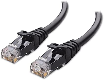
Figure 9: Ethernet Cable.
5.6.2. FIRE 2 Ethernet Cable Adapter
This special cable “breaks out” the HD-26 connector on the left side of the neoVI’s to three connectors that are used to communicate with vehicle networks. The cable is illustrated in Figure 10, while the network interface connectors are described further below.
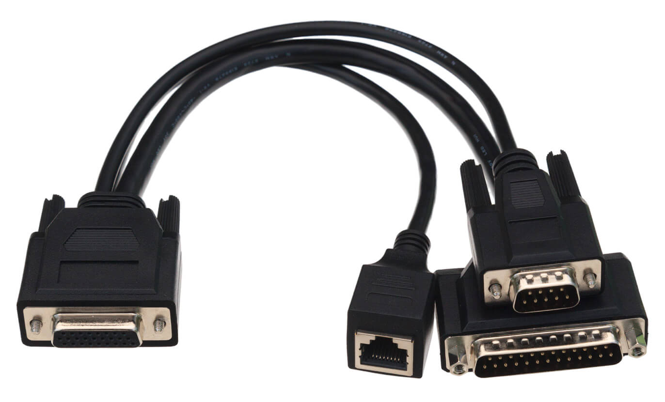
Figure 10: Fire 2 Ethernet Cable Adapter. This cable allows the neoVI’s to connect to vehicle networks and receive its primary power input.
5.6.3. DB-25 Connector
This is the main vehicle network interface connector, carrying CAN, LIN and Ethernet messages, as well as providing power to the neoVI’s from the network (Figure 11). As we’ll see later in the manual, it is also used to connect an additional cable for OBD applications.
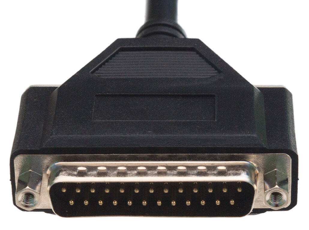
Figure 11: DB-25 Connector. This connector carries main network traffic and primary DC power to the neoVI’s.
5.6.4. DB-9 Connector
This connector carries 4 LIN channels for LIN applications (Figure 12).
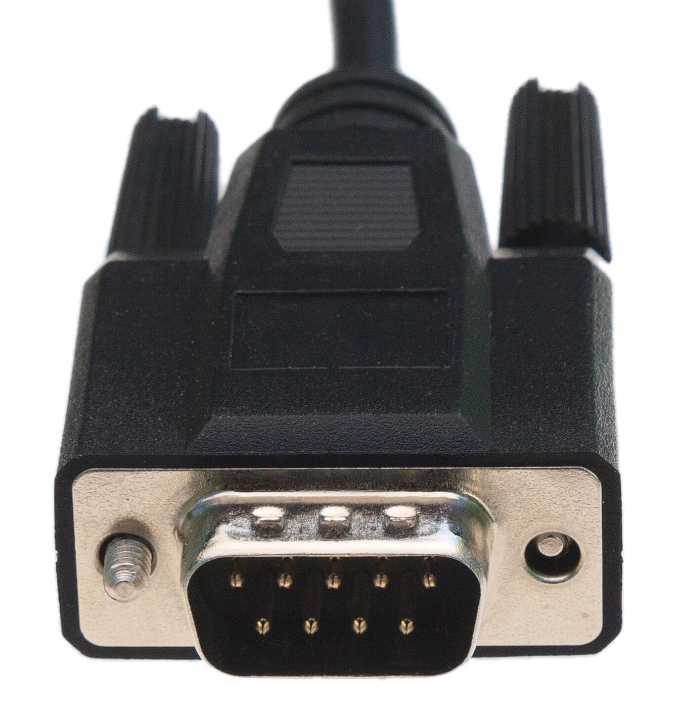
Figure 12: DB-9 Connector. This industry-standard connector carries LIN traffic
5.6.5. RJ-45 Connector
This female RJ-45 socket is used to attach a standard Ethernet cable for Automotive Ethernet and DoIP applications (Figure 13).
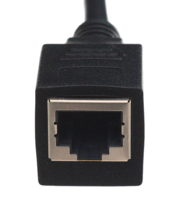
Figure 13: RJ-45 Socket.
5.6.6. USB 3.0 Gigabit Ethernet Adapter
The RED 2 comes with a Gigabit Ethernet Adapter incase your computer doesn’t have a Ethernet connection
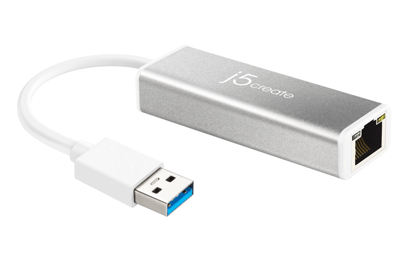
Figure 14: USB 3.0 Gigabit Ethernet Adapter
5.6.7. OBD Cables
The neoVI device comes with your choice of one of the nine OBD cables, which are used to interface the device to a vehicle or bench OBD port. Four of these cables attach to the DB-25 connector on the RED 2 / Fire 3 Ethernet Cable Adapter (Figure 13), while the fifth actually takes the place of that cable, connecting directly to the neoVI’s.
See Section 4.3 for hookup diagrams that show how to connect all of these cables to the neoVI’s and your network or bench
5.6.8. neoVI-OBD-1 Cable
This cable, which has a red OBD-II connector, is used primarily for General Motors vehicles. It can be seen in Figure 15.
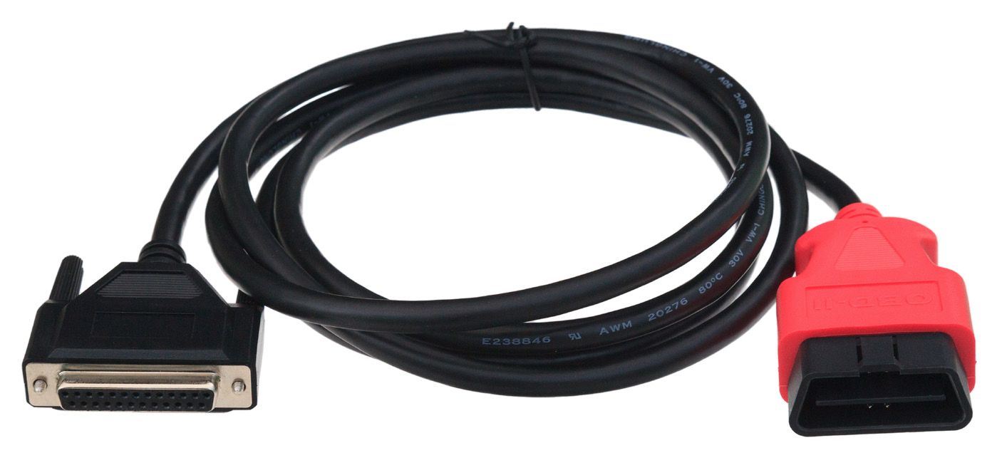
Figure 15: neoVI-OBD-1 Cable.
5.6.9. neoVI-OBD-MULTI Cable
This cable has a standard black OBD-II connector and is suitable for use with the vehicles of most OEMs. It is pictured in Figure 16.
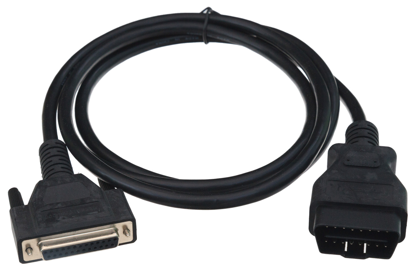
Figure 16: neoVI-OBD-MULTI Cable
5.6.10. neoVI-OBD-MULTI Right Angle Cable
This is the same as the neoVI-OBD-MULTI cable but terminates with a right-angled OBD II connector for vehicles where this is required. A picture of the cable is shown in Figure 17.
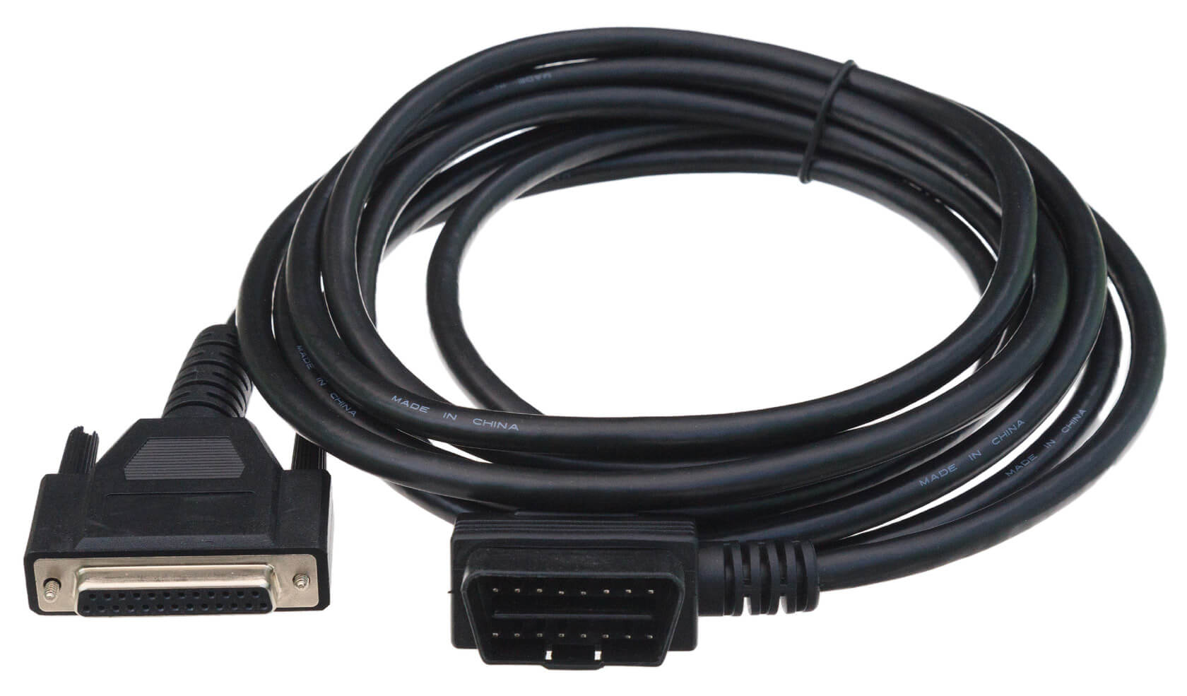
Figure 17: neoVI-OBD-MULTI Right Angle Cable.
5.6.11. neoVI FIRE/RED J1939 Cable
This cable terminates in a round 9-pin Deutsch connector for use in commercial vehicles (Figure 18).
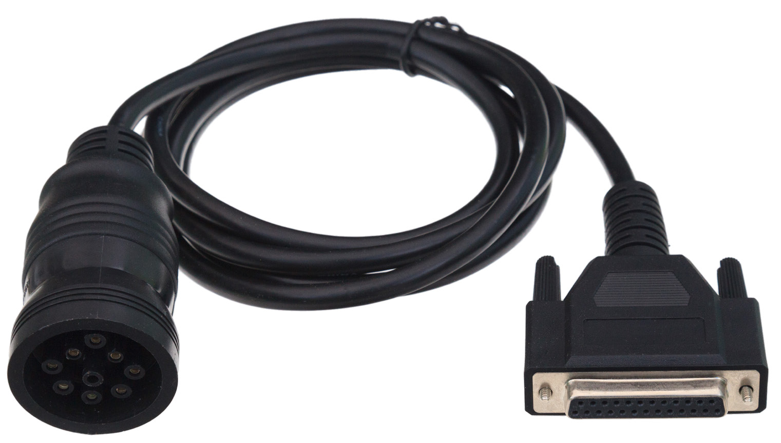
Figure 18: neoVI FIRE/RED J1939 Cable.
5.6.12. neoVI FIRE 2 OBD Cable with DoIP Support
This special cable attaches to the RED 2’s HD-26 connector in place of the regular RED 2 / Fire 3 Ethernet Cable Adapter. It contains DB-25, DB-9 and OBD-II connectors wired for DoIP use, and is illustrated in Figure 19
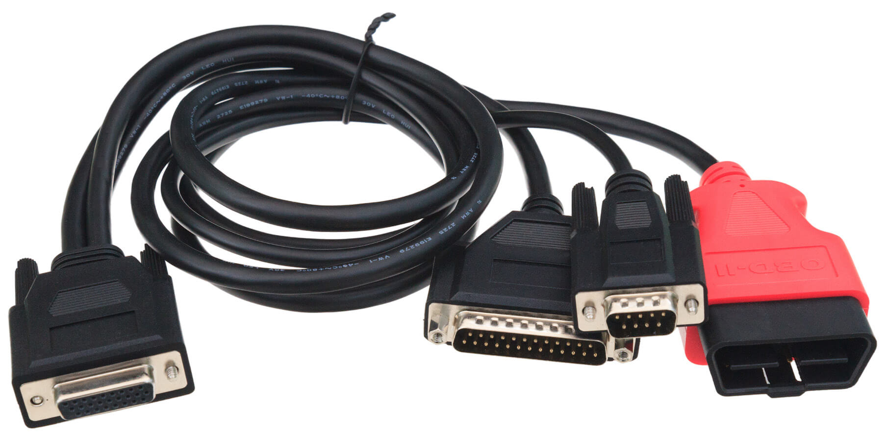
Figure 19: neoVI FIRE/RED J1939 Cable.