5. ICS Device Manager
ICS Device Manager is Intrepid’s newest cross-platform utility for managing and configuring Intrepid’s hardware. It is an integral part of Vehicle Spy, but for those not using Vehicle Spy software, it is also available as a stand alone application .
Some older Intrepid hardware is not compatible with ICS Device Manager. If using older hardware, or using an older version of Vehicle Spy prior to the release of ICS Device Manager, neoVI Explorer can still be used. Documentation for installation and use of this legacy software can be found in the The neoVI Explorer Configuration Utility section of the documentation.
5.1. Starting and Using ICS Device Manager
5.1.1. Starting ICS Device Manager from within Vehicle Spy
There are several ways to open ICS Device Manager from within VSpy. These are probably the two easiest, since they are accessible at all times:
Menu Item: Click the Setup menu and then select Hardware.
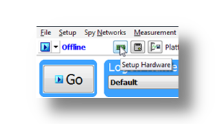
Hardware Setup Button: Click the button located in the main Vehicle Spy toolbar just under its menu (Figure below).
Note
ICS Device Manager cannot be launched when Vehicle Spy is online (even if in simulation mode). Attempting to do so, VSpy will display a prompt to either go offline and launch ICS Device Manager, or remain online and return to Vehicle Spy.
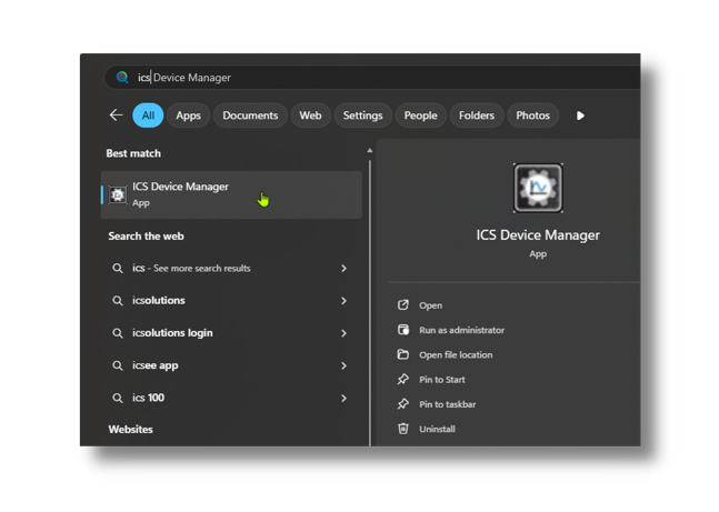
5.1.2. Starting ICS Device Manager as a Standalone Program
ICS Device Manager can be opened as standalone program. The easiest way to do this is use the search function on the Windows Start Menu as shown below.
5.2. Using ICS Device Manager
5.2.1. Discovering Devices
When ICS Device Manager loads, it will discover any connected Intrepid devices and display them along with their serial number in a drop-down menu under the File and Help menus on the top left. If a device is not listed, it may be necessary to press the “Refresh Devices” button to the right of the drop down menu. If a device is still not listed, it may be necessary to check the device’s power or connection to the host computer.
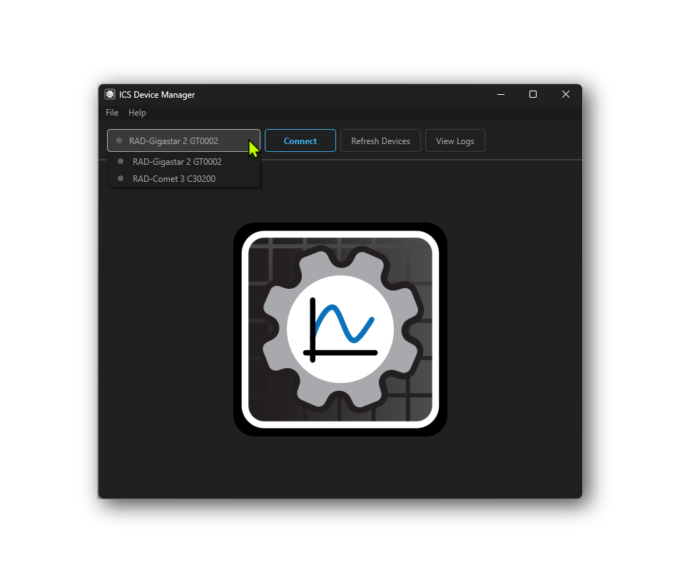
5.2.2. Connecting to a Device
To connect a device, select it from the drop-down menu and press the “Connect” button. This will connect to the device, the small indicator to the left of the device name will change from grey to green, and the “Connect” button will change to “Disconnect”. The device will remain connected until the “Disconnect” button is used to close the connection. Note that multiple devices can be connected at the same time, but only one device can be active in the user interface at a time.
Once connected, the Device Info screen will be shown, which displays information about the device such as Hardware Version, Firmware Version, Serial Number, and more. There are buttons to the top right to refresh the device information or copy the information to the clipboard.
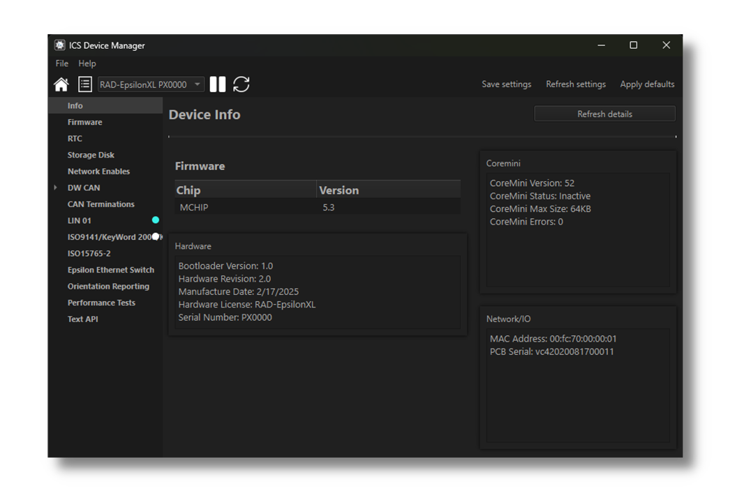
Note that this screen varies in content between Intrepid devices.
5.2.3. Viewing Activity Logs and Errors
If there are problems, pressing the “View Logs” button will show a log of recent activity and errors that may be helpful for troubleshooting. Right click on any log entry to copy it to the clipboard. Press the “Clear Logs” button to clear the log history and “Clear Errors” to clear the error history.
5.2.4. Reading and Writing Device Settings
The following commands are available in the menu at the top of the screen when a device is connected:
Read Settings: This will read the current settings from the device and update the values shown in ICS Device Manager. This is useful for undoing any changes made in ICS Device Manager that have not yet been saved to the device.
Save Settings: This will write any changes made in ICS Device Manager to the device. Until this button is pressed, any changes made in ICS Device Manager are only stored in the software and have not yet been sent to the device.
Apply Defaults: This will write the default settings to the device and then read them back for confirmation.
Warning
Note that any changes made in ICS Device Manager will not be saved to the device until the *”Save Settings”** button is pressed.*
5.2.5. Menu Bar
At the top of the window there is a menu bar with 3 menus.

5.3. Firmware Updates
5.3.1. Automatic Firmware Updates
Unlike neoVI Explorer, the legacy config tool, Device Manager does not have the ability to automatically check for and update firmware. All firmware updates must be initiated manually by the user.
5.3.2. Manual Firmware Updates
There is a slightly different interface for firmware updates depending on if the Device Manager was launched from Vehicle Spy or launched as a standalone application. The following sections show how to update the firmware in each case.
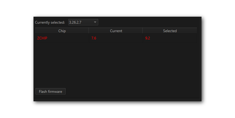
Device Manager launched from Vehicle Spy
This page shows which firmware version is currently in the device as well as the versions available for update. If Device Manager was launched from Vehicle Spy, the version of firmware released with the current version of Vehicle Spy will be display. Pressing “Flash Firmware” will update the device to this version.
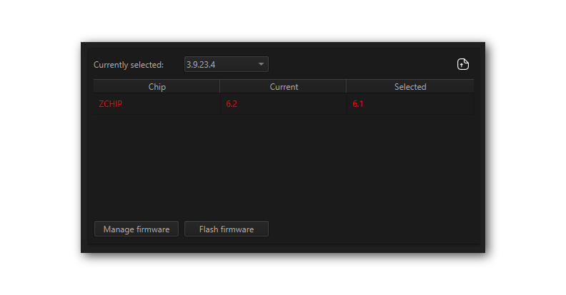
Device Manager Launched Standalone
If Device Manager was launched as a standalone application, the interface has 3 differences.
The drop down menu will be populated with any versions of firmware that are stored locally on the computer.
A button exists in the top right corner to import firmware from a file (
).
There will be a “Manage Firmware” button.
Firmware Manager
Pressing the “Manage Firmware” button will open a new dialog box (below). The “Remote” tab has a drop down menu listing versions of firmware that can be downloaded from Intrepid’s server. After selecting the desired version, check the box(es) next to the device(s) desired and press the “Download” button.
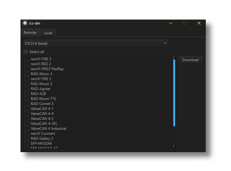
The “Local” tab is a similar interface for deleting versions of firmware that have already been downloaded.
5.3.3. The Firmware Update Process
Problems updating firmware over USB
If problems are encountered updating a device using USB, try removing any USB hubs and connect the device directly to the computer
During the firmware update process, the device will be placed into bootloader mode, indicated by all LEDs on the top label flashing synchronously. Normal LED flash patterns will resume when the update is complete and the device reboots. The progress of the firmware update operation is displayed in a dialog box as shown below. When the process is complete the dialog box will disappear a message will appear in Device Manager to confirm that the update has finished. If any error messages are displayed or any other problems experienced updating the device’s firmware, please contact Customer Support for assistance.
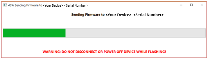
Warning
Please take heed of the warning on the firmware update dialog box: leave the device connected and powered on for the entire firmware update process to avoid possible problems with the device.
5. Ethernet PHY and Switch Firmware Flasher
In addition to the firmware providing the primary functionality of the device, there is also firmware that runs on the Ethernet PHYs and switch devices. Updates for this firmware are rare and only necessary if recommended by Intrepid’s or Infineon’s support team. If an update is necessary, firmware files may obtained from Infineon and used with this interface.
After selecting the desired firmware file and device to be flashed, press the flash button to perform the update.
5.4. RTC
This device contains a Real-Time Clock (RTC) that is the time base for data logging and other time-sensitive operations. The RTC is powered by a small battery, which allows it to maintain the current time and date even when the main power supply is disconnected.
This interface allows you to read the current time and date from the RTC, as well as synchronize it with the host computer’s time.

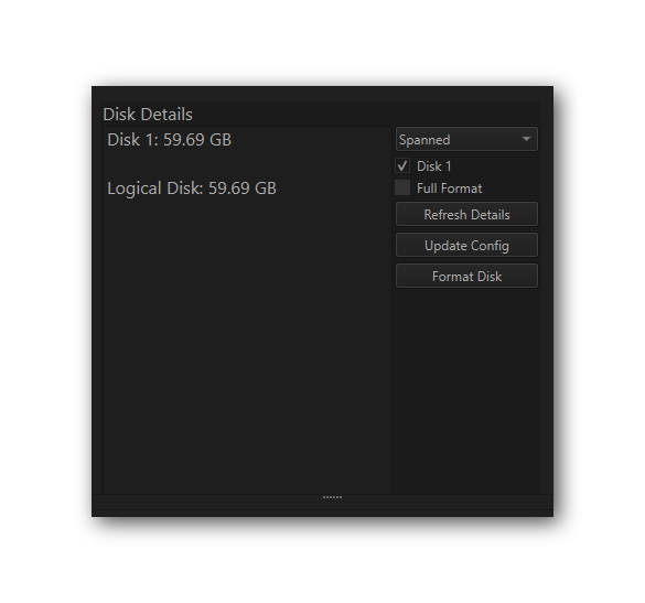
5.5. Storage Disk
This interface is used to format and configure the device’s non-volatile memory.
RAD Epsilon-XL uses the non-volatile memory to store coremini scripts to be run standalone on the device’s embedded processor.
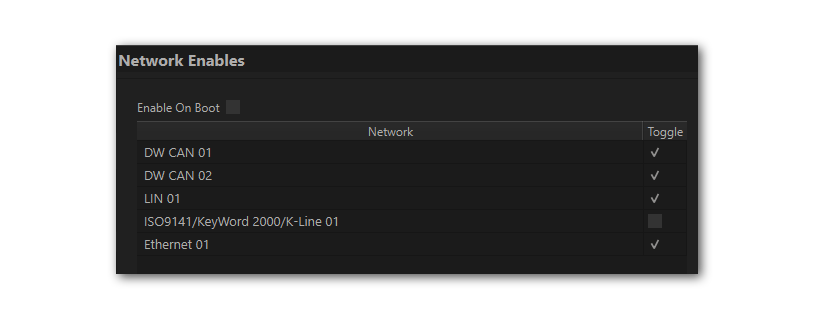
5.6. Network Enables
All device networks can be enabled or disabled in this branch of the configuration tree. The enabling/disabling that can be done here is redundant with what can be done in the network specific branches in Device Manager.
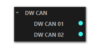
5.7. CAN Network Settings
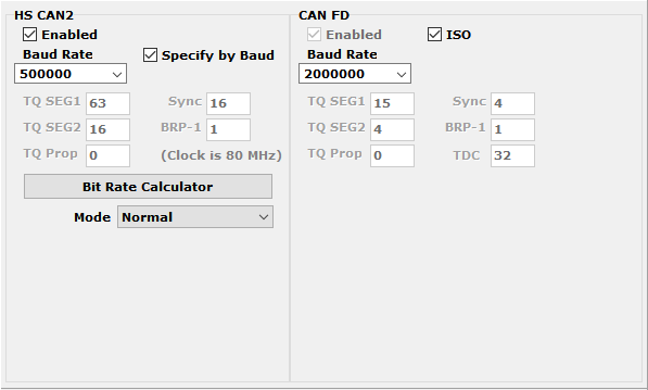
This area of Device Manager is used to enable, disable and configure the High Speed CAN channels. Each channel has an entry under the “CAN” group (which cannot be clicked itself). The current status of each channel is shown next to its name; a cyan circle indicates that the channel is enabled, while a white circle indicates disabled.
5.7.1. Port Configuration
All of the CAN channels have the same parameters, which can be configured using the controls in the right-hand pane; the default settings are shown below.
Enabled |
The checkbox next to the port name at the top of the configuration page is used to enable or disable the port. When disabled, all of the other parameter controls cannot be edited. |
Mode |
This drop down menu sets the port to operate in normal or listen-only mode. |
Timing Mode |
Baud Rate: The baud rate of the channel is set by a drop down menu. (Note that this drop down menu is disabled if the port is disabled or if Timing Mode is set to TQ Timing.) |
TQ Timing: The operation of the CAN channel is based on these five settings: TQ SEG1, TQ SEG2, TQ Prop, Sync, BRP-1. CAN FD has one additional setting in TQ Timing Mode, TDC. This stands for Transmitter Delay Compensation. When enabled, the device will attempt to compensate for the delay between when a message is sent and when it is actually put on the CAN bus. This can help improve the timing of messages on the bus, especially at higher data rates. The TDC value is used to specify the amount of compensation applied, and the default value is 0. This setting is only applicable to CAN FD operation. |
|
FD Enabled |
When checked, the network operates in CAN FD mode, allowing for faster data rates and larger data payloads. When unchecked, the network operates in classic CAN mode. |
FD ISO |
When checked, CAN FD messages are formatted according to the ISO 11898-1 standard. When unchecked, CAN FD messages are formatted according to the non-ISO CAN FD format. |
Disable Automatic Retransmission |
When checked, the device will not automatically attempt to retransmit messages that fail to send successfully. This can be useful for testing error handling in the software, but in normal operation it should be left unchecked so that messages are automatically retransmitted until they are sent successfully. |
TQ Timing Mode
These settings are for advanced users and normally should be left at their default values.
5.7.2. CAN Termination
This lists all of the CAN channels in the device having software selectable termination. The checkboxes enable and disable this termination.

5.8. LIN Network Settings
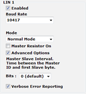
This section of Device Manager allows enabling, disabling and configuring its LIN channels. As with the CAN channels, a cyan circle indicates that the channel is enabled, while a white circle indicates disabled.

All of these channels have the same parameters, which can be seen below. In this image we have selected the Advanced Options checkbox to display its options (described below).
Enabled |
The checkbox next to the port name at the top of the configuration page is used to enable or disable the port. When disabled, all of the other parameter controls cannot be edited. |
|
Master Resistor On |
Enable this option for the device to act as the master on the specified LIN bus. |
|
Baud Rate |
This drop-down menu sets baud rate. The default is 10417. |
|
Mode |
Normal |
Normal slew rate (20Kbps) |
Slow |
Slow slew rate for better EMC performance (10Kbps) |
|
Fast |
Fast slew rate for faster data rates (>100Kbps) |
|
Sleep |
Bus driver off |
|
Advanced Options |
Master Slave Interval |
The time between the master ID and the first slave byte, in bits (default 0). |
Verbose Error Reporting |
When checked, break errors and other error messages from the LIN driver are displayed. |
|
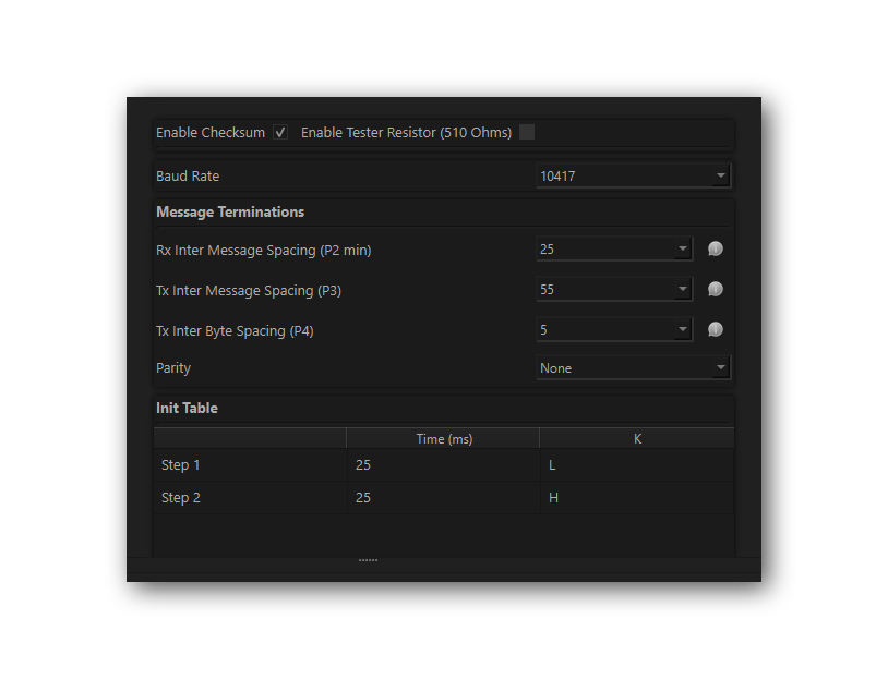
5.9. ISO 9141 / Keyword 2000 / K-Line
This interface is to configure the ISO 9141 / Keyword 2000 / K-Line communication settings. It is a single-wire interface that operates at a baud rate of 10.4 kbps.
5.10. ISO 15765-2
This page contains one setting: IFS Shift Register. Changing this from its default value of 0 causes time to be added to the Inner Frame Spacing of USDT frames transmitted by CoreMini scripts running in the neoVI’s device. The number entered is multiplied by 6.4 µs to determine the time offset. The allowed range is -1563 to 1563.

5.11. PHY Configuration
5.11.1. Using Device Manager
The following interface is used to configure the PHY of each port of the 88Q6113.
There are separate tabs for Switch A and Switch B PHYs
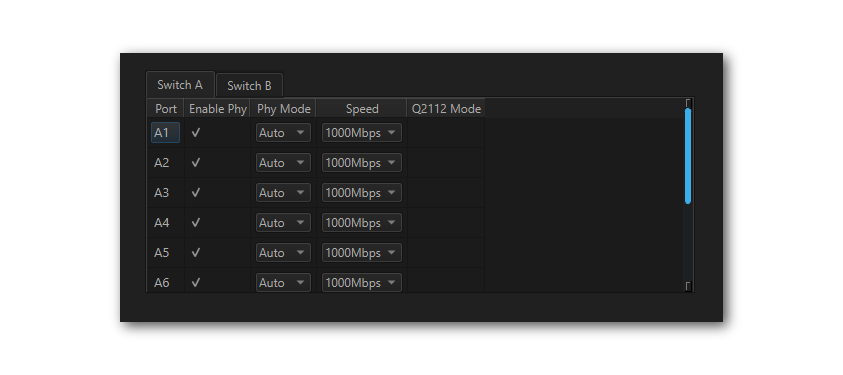
The following interface is used to configure the PHY of each port of the 88Q6113.
Enable PHY |
Each PHY can be independently enabled/disabled |
Auto/Master/Slave |
Master/Slave setting for each PHY |
Speed |
100/1000 Mbps for ports A1-A8, B1-B8, B11 |
100/1000/10000 Mbps for ports A9/B9 |
|
Q2112 Mode |
Does not apply to EpsilonXL |
5.11.2. Using libicsneo
The PHYs can also be configured using libicsneo . Follow this link for an example in Python
5.12. Reporting
This enables reporting of device orientation.

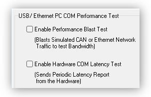
5.13. Performance Tests
The following are tests which can be used to characterize the bandwidth and latency between ICS hardware and its host computer. If problem is encountered with either of these, our Customer Support would be happy to help resolve it. Reference the end of this document for contact information.
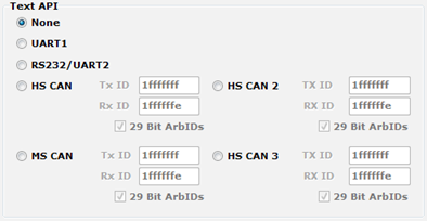
5.14. Text API
These parameters control the operation of the text API that can be used to operate the neoVI FIRE 2 using third party software. Please contact Intrepid Customer Support if any assistance using the API is required.