5. ICS Device Manager
ICS Device Manager is Intrepid’s newest cross-platform utility for managing and configuring Intrepid’s hardware. It is an integral part of Vehicle Spy, but for those not using Vehicle Spy software, it is also available as a stand alone application.
Some older Intrepid hardware is not compatible with ICS Device Manager. If using older hardware, or using an older version of Vehicle Spy prior to the release of ICS Device Manager, neoVI Explorer can still be used. Documentation for installation and use of this legacy software can be found in the The neoVI Explorer Configuration Utility section of the documentation.
5.1. Starting and Using ICS Device Manager
5.1.1. Starting ICS Device Manager from within Vehicle Spy
There are several ways to open ICS Device Manager from within VSpy. These are probably the two easiest, since they are accessible at all times:
Menu Item: Click the Setup menu and then select Hardware.
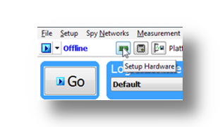
Hardware Setup Button: Click the button located in the main Vehicle Spy toolbar just under its menu (Figure below).
Note
ICS Device Manager cannot be launched when Vehicle Spy is online (even if in simulation mode). Attempting to do so, VSpy will display a prompt to either go offline and launch ICS Device Manager, or remain online and return to Vehicle Spy.
5.1.2. Starting ICS Device Manager as a Standalone Program
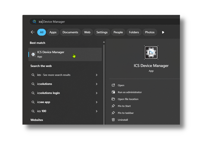
ICS Device Manager can be opened as standalone program. The easiest way to do this is use the search function on the Windows Start Menu as shown below.
5.2. Using ICS Device Manager
5.2.1. Discovering Devices
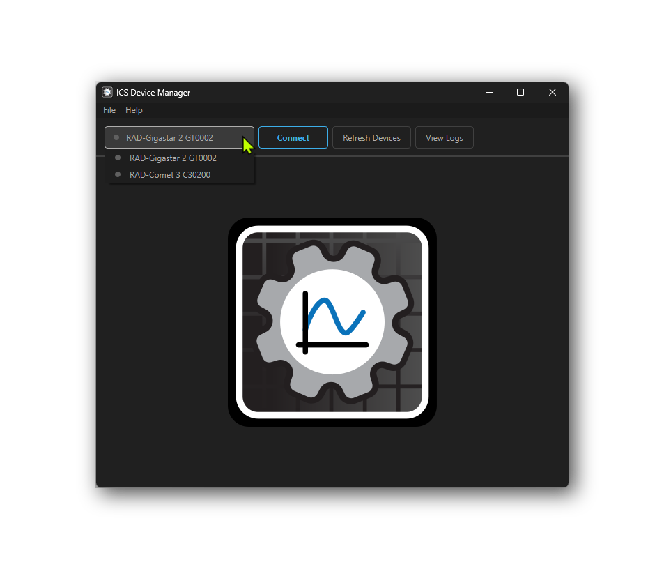
When ICS Device Manager loads, it will discover any connected Intrepid devices and display them along with their serial number in a drop-down menu under the File and Help menus on the top left. If a device is not listed, it may be necessary to press the “Refresh Devices” button to the right of the drop down menu. If a device is still not listed, it may be necessary to check the device’s power or connection to the host computer.
5.2.2. Connecting to a Device
To connect a device, select it from the drop-down menu and press the “Connect” button. This will connect to the device, the small indicator to the left of the device name will change from grey to green, and the “Connect” button will change to “Disconnect”. The device will remain connected until the “Disconnect” button is used to close the connection. Note that multiple devices can be connected at the same time, but only one device can be active in the user interface at a time.
Once connected, the Device Info screen will be shown, which displays information about the device such as Hardware Version, Firmware Version, Serial Number, and more. There are buttons to the top right to refresh the device information or copy the information to the clipboard.
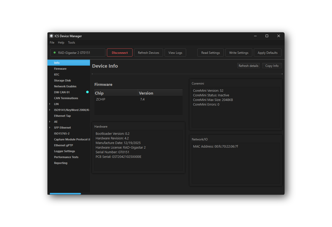
Note that this screen varies in content between Intrepid devices.
5.2.3. Viewing Activity Logs and Errors
If there are problems, pressing the “View Logs” button will show a log of recent activity and errors that may be helpful for troubleshooting. Right click on any log entry to copy it to the clipboard. Press the “Clear Logs” button to clear the log history and “Clear Errors” to clear the error history.
5.2.4. Reading and Writing Device Settings
The following commands are available in the menu at the top of the screen when a device is connected:
Read Settings: This will read the current settings from the device and update the values shown in ICS Device Manager. This is useful for undoing any changes made in ICS Device Manager that have not yet been saved to the device.
Save Settings: This will write any changes made in ICS Device Manager to the device. Until this button is pressed, any changes made in ICS Device Manager are only stored in the software and have not yet been sent to the device.
Apply Defaults: This will write the default settings to the device and then read them back for confirmation.
Warning
Note that any changes made in ICS Device Manager will not be saved to the device until the *”Save Settings”** button is pressed.*
5.2.5. Menu Bar
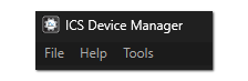
At the top of the window there is a menu bar with 3 menus.
5.3. Firmware Updates
5.3.1. Automatic Firmware Updates
Unlike neoVI Explorer, the legacy config tool, Device Manager does not have the ability to automatically check for and update firmware. All firmware updates must be initiated manually by the user.
5.3.2. Manual Firmware Updates
There is a slightly different interface for firmware updates depending on if the Device Manager was launched from Vehicle Spy or launched as a standalone application. The following sections show how to update the firmware in each case.
Device Manager launched from Vehicle Spy
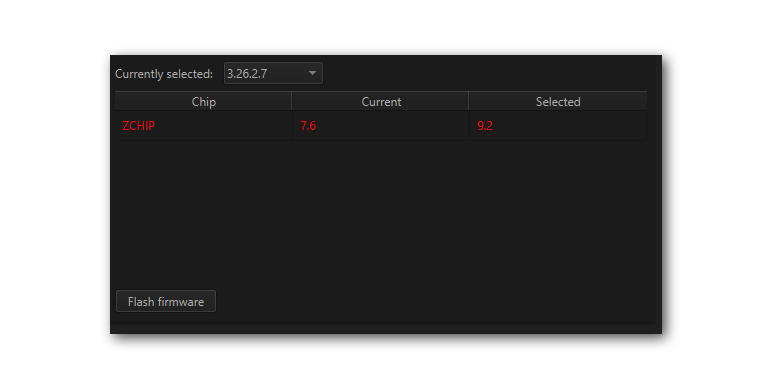
This page shows which firmware version is currently in the device as well as the versions available for update. If Device Manager was launched from Vehicle Spy, the version of firmware released with the current version of Vehicle Spy will be display. Pressing “Flash Firmware” will update the device to this version.
Device Manager Launched Standalone
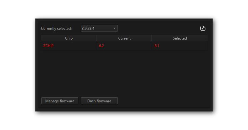
If Device Manager was launched as a standalone application, the interface has 3 differences.
The drop down menu will be populated with any versions of firmware that are stored locally on the computer.
A button exists in the top right corner to import firmware from a file (
).
There will be a “Manage Firmware” button.
Firmware Manager
Pressing the “Manage Firmware” button will open a new dialog box (below). The “Remote” tab has a drop down menu listing versions of firmware that can be downloaded from Intrepid’s server. After selecting the desired version, check the box(es) next to the device(s) desired and press the “Download” button.
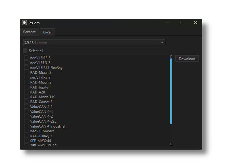
The “Local” tab is a similar interface for deleting versions of firmware that have already been downloaded.
5.3.3. The Firmware Update Process
Problems updating firmware over USB
If problems are encountered updating a device using USB, try removing any USB hubs and connect the device directly to the computer
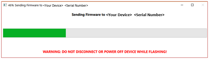
During the firmware update process, the device will be placed into bootloader mode, indicated by all LEDs on the top label flashing synchronously. Normal LED flash patterns will resume when the update is complete and the device reboots. The progress of the firmware update operation is displayed in a dialog box as shown below. When the process is complete the dialog box will disappear a message will appear in Device Manager to confirm that the update has finished. If any error messages are displayed or any other problems experienced updating the device’s firmware, please contact Customer Support for assistance.
Warning
Please take heed of the warning on the firmware update dialog box: leave the device connected and powered on for the entire firmware update process to avoid possible problems with the device.
5.3.4. Select Firmware Variant
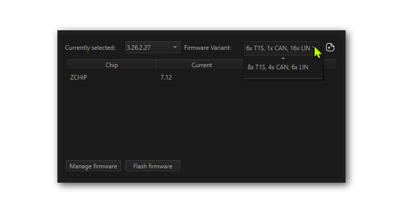
RAD-Gigastar2 has two firmware variants that enable some networks at the expense of disabling other networks. A summary of the networks available is shown
MAX LIN: Maximum number of LIN channels with a reduced count of 10BASE-T1S and CAN ports.
MAX T1S/CAN: A reduced number of LIN channels to enable the maximum number of 10BASE-T1S and CAN ports.
MAX LIN Configuration |
MAX T1S/CAN Configuration |
|
1000BASE-T1 (Marvell 88Q222xM) |
2 |
2 |
1Gbps SFP Ports (1000BASE-X/SGMII) |
2 |
2 |
10BASE-T1S (ADI AD330X) |
6 |
8 |
CAN-FD |
1 |
4 |
LIN /K-Line |
16 |
6 |
DoIP Activation Line |
1 |
1 |
The interface shown below is used to change which firmware variant is used, and consequently which networks are available. After selecting the desired firmware variant in the drop-down menu, press the “Update” button to send the firmware to the RAD-Gigastar2.
5.4. RTC
This device contains a Real-Time Clock (RTC) that is the time base for data logging and other time-sensitive operations. The RTC is powered by a small battery, which allows it to maintain the current time and date even when the main power supply is disconnected.
This interface allows you to read the current time and date from the RTC, as well as synchronize it with the host computer’s time.

5.5. Storage Disk
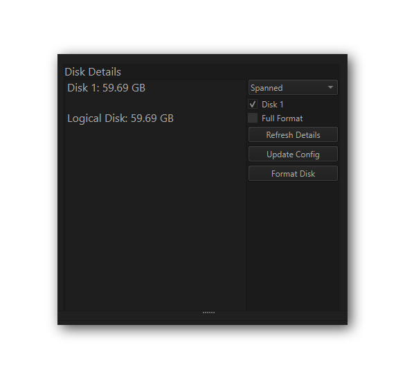
This interface is used to format and configure the device’s non-volatile memory.
5.6. Network Enables
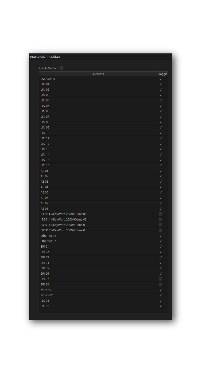
All device networks can be enabled or disabled in this branch of the configuration tree. The enabling/disabling that can be done here is redundant with what can be done in the network specific branches in Device Manager.
5.7. CAN Network Settings
This area of Device Manager is used to enable, disable and configure the High Speed CAN channels. Each channel has an entry under the “CAN” group (which cannot be clicked itself). The current status of each channel is shown next to its name; a cyan circle indicates that the channel is enabled, while a white circle indicates disabled.
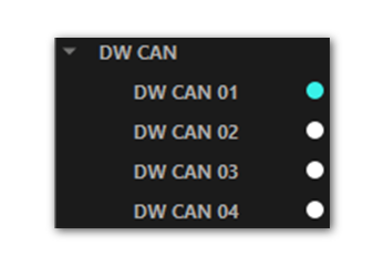
5.7.1. Port Configuration
All of the CAN channels have the same parameters, which can be configured using the controls in the right-hand pane; the default settings are shown below.
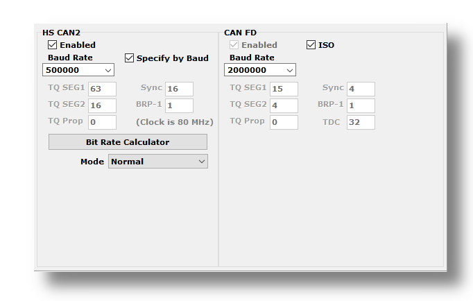
Enabled |
The checkbox next to the port name at the top of the configuration page is used to enable or disable the port. When disabled, all of the other parameter controls cannot be edited. |
Mode |
This drop down menu sets the port to operate in normal or listen-only mode. |
Timing Mode |
Baud Rate: The baud rate of the channel is set by a drop down menu. (Note that this drop down menu is disabled if the port is disabled or if Timing Mode is set to TQ Timing.) |
TQ Timing: The operation of the CAN channel is based on these five settings: TQ SEG1, TQ SEG2, TQ Prop, Sync, BRP-1. CAN FD has one additional setting in TQ Timing Mode, TDC. This stands for Transmitter Delay Compensation. When enabled, the device will attempt to compensate for the delay between when a message is sent and when it is actually put on the CAN bus. This can help improve the timing of messages on the bus, especially at higher data rates. The TDC value is used to specify the amount of compensation applied, and the default value is 0. This setting is only applicable to CAN FD operation. |
|
FD Enabled |
When checked, the network operates in CAN FD mode, allowing for faster data rates and larger data payloads. When unchecked, the network operates in classic CAN mode. |
FD ISO |
When checked, CAN FD messages are formatted according to the ISO 11898-1 standard. When unchecked, CAN FD messages are formatted according to the non-ISO CAN FD format. |
Disable Automatic Retransmission |
When checked, the device will not automatically attempt to retransmit messages that fail to send successfully. This can be useful for testing error handling in the software, but in normal operation it should be left unchecked so that messages are automatically retransmitted until they are sent successfully. |
TQ Timing Mode
These settings are for advanced users and normally should be left at their default values.
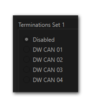
5.7.2. CAN Termination
The RAD-Gigastar2 has a single CAN termination that can be enabled on one of the 4 CAN channels. (note that only one CAN channel will be shown depending on which version of firmware is installed on the device)
5.8. LIN Network Settings
This section of Device Manager allows enabling, disabling and configuring its LIN channels. As with the CAN channels, a cyan circle indicates that the channel is enabled, while a white circle indicates disabled.
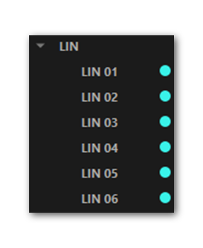
Note: RAD-Gigastar2 may have 6 or 16 LIN channels, depending on the version of firmware installed.
All of these channels have the same parameters, which can be seen below. In this image we have selected the Advanced Options checkbox to display its options (described below).

Enabled |
The checkbox next to the port name at the top of the configuration page is used to enable or disable the port. When disabled, all of the other parameter controls cannot be edited. |
|
Master Resistor On |
Enable this option for the device to act as the master on the specified LIN bus. |
|
Baud Rate |
This drop-down menu sets baud rate. The default is 10417. |
|
Mode |
Normal |
Normal slew rate (20Kbps) |
Slow |
Slow slew rate for better EMC performance (10Kbps) |
|
Fast |
Fast slew rate for faster data rates (>100Kbps) |
|
Sleep |
Bus driver off |
|
Advanced Options |
Master Slave Interval |
The time between the master ID and the first slave byte, in bits (default 0). |
Verbose Error Reporting |
When checked, break errors and other error messages from the LIN driver are displayed. |
|
5.9. Ethernet Tap Configurations
From this interface, the Ethernet ports can be configured as combination of active taps and Independent Ports as described in earlier in this guide.
To create a tap, select the first port using dropdown menu  ,
then select the second port using dropdown menu
,
then select the second port using dropdown menu  ,
and press the “Create Tap” button
,
and press the “Create Tap” button  . The new tap will appear in the list of tap pairs below.
A tap can be deleted pressing the “Remove” button
. The new tap will appear in the list of tap pairs below.
A tap can be deleted pressing the “Remove” button  .
.
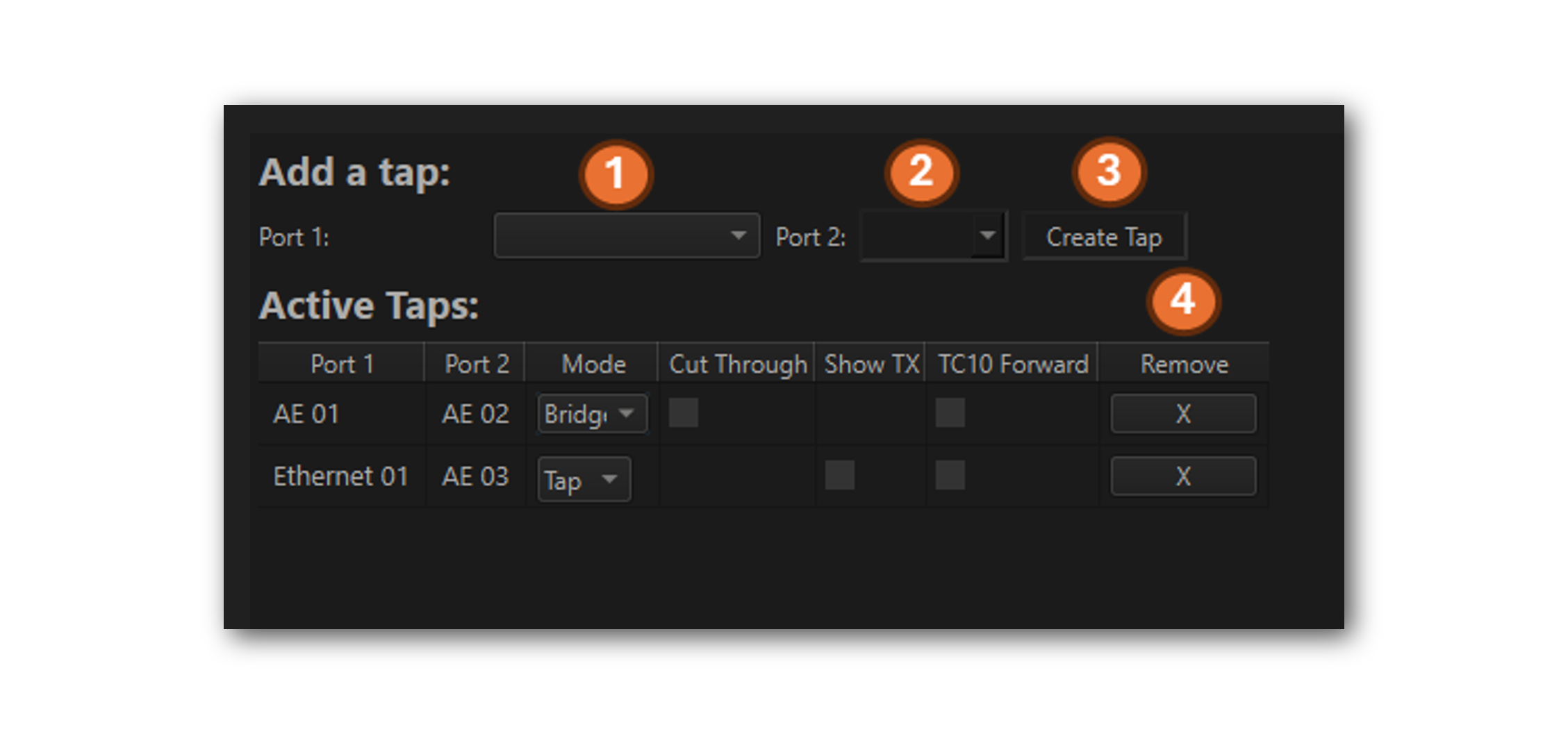
Once a tap is created, the available configurations will be displayed in the list of active taps.
5.9.1. Mode
The default mode is an active tap. The pair of ports can be configured as a bridge, which operates exactly as a tap, except that messages are not processed and sent to the host computer, logger, or embedded scripts. This mode is useful when the device is being used as a simple media converter or the aggregate traffic through the device exceeds the capacity of the host computer or logger.
If any port of the tap is 10BASE-T1S, the bridge option will not be available.
5.9.2. Cut Through
(only available for select tap pairs)
By default, a tap operates in a mode known as “Store-and-Forward”. This means the entire frame ingresses on the receiving port before it is sent out the other port of the tap pair. This mode allows the injection of messages from the host computer of the RAD-Gigastar2 or from an embedded script.
Store-and-Forward mode introduces latency that is a function of the length of a frame. In many cases, this latency does not affect the proper function of the devices being tapped. If this latency is suspected to be a problem, this setting configures the tap to operate in “cut-through” mode. This means that the received frame will start egressing with minimal and deterministic latency added. The tradeoff for operating in this mode is that no messages may be injected by the tap.
The latencies added between AE 01 and AE 02 in cut-through tap mode are as follows:
MACsec Disabled |
(Authentication only, no encryption) |
|
100 Mbps |
~ 2.5 µs |
~46.2µs |
1 Gbps |
~ 5.5 µs |
~10 µs |
Using Active Taps with gPTP
Depending on its configuration, gPTP may be affected by “Store-and-Forward” operation. If problems are encountered with gPTP, enable Cut-Through mode to determine if the latency associated with “Store-and-Forward” operation is the root cause
5.9.3. Show TX
(only available for select tap pairs)
When in tap mode, the device normally only shows frames received on the RX side of the tap pair. Enabling this setting causes the frames transmitted from the TX side of the tap pair to also be shown. This is useful for debugging PHY-level issues where the transmitted frames need to be observed.
Due to the hardware architecure of some devices, this setting is only available for select tap pairs. If the setting is not available, a checkbox will not be displayed.
5.9.4. TC10 Forwarding
TC10 is a signalling done between PHYs in support of managing the sleep/wake state of a vehicle.
TC10 uses special symbols in its PHY-to-PHY signalling of sleep and wake requests. These symbols are not Ethernet frames, and consequently do not natively pass through an active tap. TC10 Forwarding ensures that the TC10 symbols are not blocked by the active tap.
Since TC10 only applies to Automotive Ethernet, this setting is only available if both ports of the tap pair are Automotive Ethernet ports.
5.10. PHY Configurations
Each Intrepid product offers a different mix of networks. Below is a tree of the available Ethernet networks on your device. The sections that follow explain how each version of Ethernet is configured.
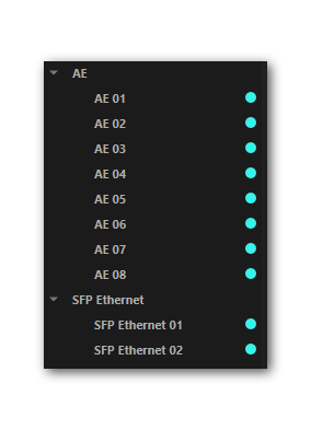
The Ethernet PHYs can be configured by selecting them in the configuration tree along the left side of the window.
Selecting a specific PHY will reveal the available configurations in the right of the window.
5.10.1. 100/1000BASE-T1 PHY Configuration (AE01-AE02)
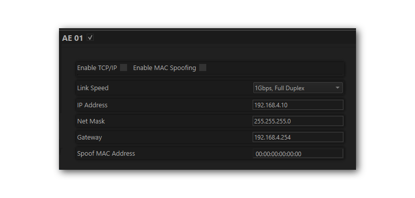
Enabled |
The checkbox next to the port name enables or disables the port. Each port can be independently enabled/disabled. |
TCP/IP Settings |
Reserved for future use. |
Enable MAC Spoofing |
When enabled, the Spoof MAC Address specified at the bottom of the page will be will be used instead of the factory assigned MAC Address of the port. |
Link Speed & Duplex |
|
Link mode |
The setting is related to the master or slave of the link to another PHY. This can also be configured to automatically determine if the PHY should be master or slave to establish a link with another PHY. |
Enabled |
The checkbox next to the port name enables or disables the port. Each port can be independently enabled/disabled. |
Preemption Support |
Enable if traffic contains frame preemption per 802.3br |
Enable MAC Spoofing |
When enabled, MAC addresses will be spoofed based on the configuration explained at the bottom of this table. |
Link mode |
The setting is related to the master or slave of the link to another PHY. This can also be configured to automatically determine if the PHY should be master or slave to establish a link with another PHY. |
Link Speed |
|
Spoofing Configuration |
After specifying “Original MAC Address” and “Spoof MAC Address”, the spoofing direction determines if the spoofing is done on the Source MAC Address or the Destination MAC address after it is received by the PHY. |
5.10.2. SFP Configurations (Ethernet-Ethernet 02)
If the RAD-Gigastar2 is hosting a 100/1000BASE-T1 in an SFP slot, the configuration is the same as ports AE01-AE02.
If the hosted SFP is 100/1000BASE-T, the configuration is as follows.
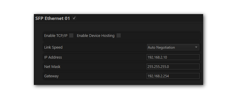
Enabled |
The checkbox next to the port name enables or disables the port. Each port can be independently enabled/disabled. |
TCP/IP Settings |
Reserved for future use. |
Enable Device Hosting |
Enables ability to host compatible IP cameras for logging |
Link Speed & Duplex |
The speed can be set to full-duplex 10, 100, 1000 Mbps, or set to auto-negotiation. |
5.10.3. 10BASE-T1S Configurations (AE 03 - AE 10)
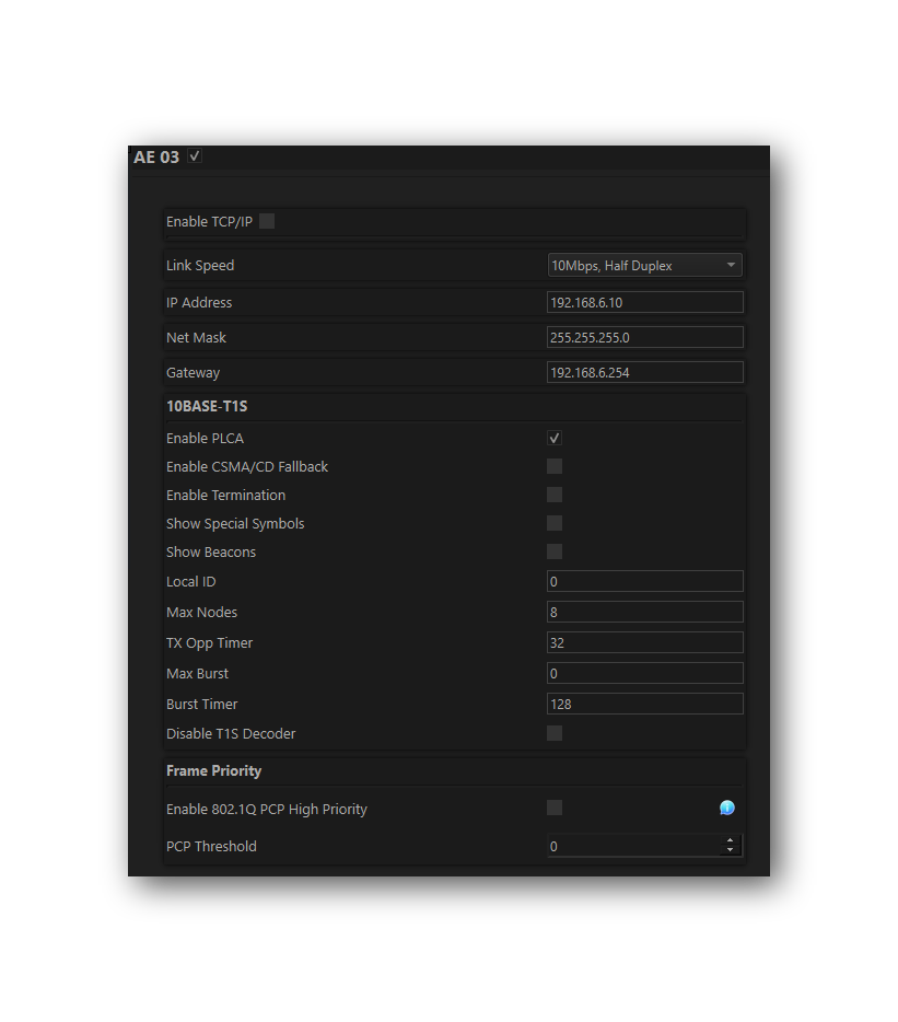
Enabled |
The checkbox next to the port name enables or disables the port. Each port can be independently enabled/disabled. |
Enable TCP/IP |
Reserved for future use |
Link Speed & Duplex |
The speed is fixed at 10Mbps, Half Duplex. |
Enable PLCA |
This enabled PLCA for the PHY. When disabled, the PHY will operate in CSMA mode. |
Enable CSMA/CD Fallback |
If the PHY is configured for PLCA, but does not receive a BEACON for more than ~13mS, the PHY will switch to CSMA/CD mode until a BEACON is received. |
Enable Termination |
This enables the 10BASE-T1S End Termination for the port. |
Show Special Symbols |
When this box is checked, all the 10BASE-T1S PLCA symbols except BEACONS will be time stamped and collected along with the Ethernet Traffic. |
Show Beacons |
When this box is checked, the 10BASE-T1S PLCA BEACONS will be time stamped and collected along with the Ethernet Traffic. |
Local ID |
The PLCA Node ID of the PHY |
Max Nodes |
The total number of nodes on the 10BASE-T1S network. |
TX Opp Timer |
The window of time which a 10BASE-T1S node has to start transmitting before the Transmit Opportunity is forfeited and the next Transmit Opportunity begins. The default is 32 bit times. |
Max Burst |
The number of burst frames a device is allowed to send in a given cycle. |
Burst Timer |
The amount of time a device has to transmit a burst frame following the end of the previous frame. If this time expires before a burst frame is sent, the cycle moves to the Transmit Opportunity of the next Node ID. |
Disable T1S Decoder |
10BASE-T1S traffic is decoded in hardware to enable the capture of PLCA symbols as well as enable more precise time stamps on the packet. This must be disabled in order to use the Frame Priority features of the MACPHY. |
Frame Priority |
The MACPHY has a second transmit buffer for high-priority traffic. When enabled, any frame having a PCP equal or greater than the PCP threshold specified will be placed in the high priority transmit buffer, having strict priority over the non-priority transmit buffer. |
Only enable logging of PLCA symbols when necessary
The logging of PLCA symbols greatly increases the amount of data collected. If this is enabled on more than one 10BASE-T1S port of your device, it may overwhelm any host computer, as well as inflate the log size of the data collected.
5.11. ISO 15765-2
This page contains one setting: IFS Shift Register. Changing this from its default value of 0 causes time to be added to the Inner Frame Spacing of USDT frames transmitted by CoreMini scripts running in the neoVI’s device. The number entered is multiplied by 6.4 µs to determine the time offset. The allowed range is -1563 to 1563.

5.12. Capture Module Protocol
Capture Module Protocol (CMP) is a low-overhead protocol used to encapsulate network traffic and stream it over Ethernet to a CMP client, typically a data logger.
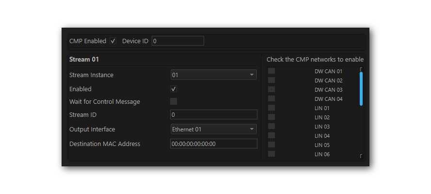
CMP Enabled |
Enables CMP on the device |
Device ID |
This is a unique ID used to differentiate loggers on the network. |
Stream Instance |
The device can support 10 independent streams. Each instance is defined by a unique stream ID, a collection of networks to stream, and an Ethernet port chosen to send the stream. |
Enabled |
Each stream instance can be enabled/disabled independently |
Wait for Control Message |
If unchecked, the device will stream CMP after booting. as opposed to waiting for a control message from the CMP client. |
Stream ID |
An identifier between 0 and 255 |
Output Interface |
Select the Ethernet port to stream CMP |
Destination MAC Address |
Destination address used in the CMP Ethernet Header |
CMP Network Selection |
On the right is a list of all networks available to stream over CMP. Checkboxes select the networks to be included in the stream instance. |
5.13. gPTP Time Synchronization
This device supports Generalized Precision Time Protocol as defined in IEEE 802.1AS. It can be configured to use the Standard profile or the Automotive profile as defined by the Avnu Alliance.
Typically the timestamp Physical Hardware Clock (PHC) of your device is synchronized with a host computer when connected. In cases where it is desirable for this clock to be synchronized with another clock source, gPTP can be enabled. The clock is automatically synchronized to Epoch Time when enabled and it is connected to a gPTP grandmaster.
Note
Erratic behavior may be observed if the Epoch Time of logged messages is prior to 1/1/2007.
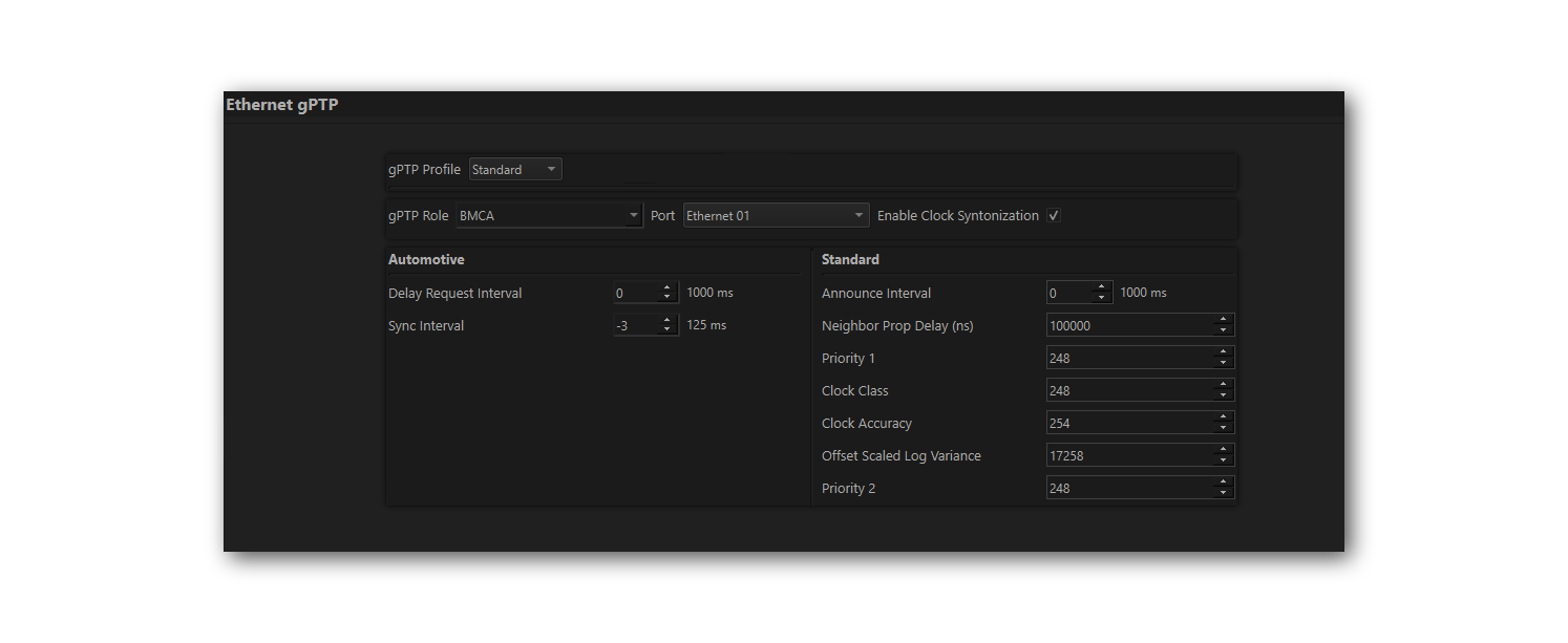
5.13.1. Common Configuration
gPTP can be configured in 1 of 2 profiles: Automotive or Standard. The configuration options for each profile are described in the sections below. The following configurations are common to both profiles:
gPTP Profile |
Standard: This profile uses the Best Master Clock Algortihm (BMCA) to determine the role of the gPTP port. The configurations of the standard profile are grouped in the bottom right. |
Automotive: In this mode, the port role is statically configured as either master or slave. The remaining configurations are grouped in the bottom left. |
|
gPTP Role |
For the Standard profile, this is set to BMCA. For Automotive, select either master or slave. |
Port |
RAD-Galaxy2: Select a single slave port OR multiple master ports. |
All other Intrepid network interfaces: Select a single slave port OR single master port |
|
Enable Clock Syntonization |
When enabled, the slave clock will use rateratio to compensate for frequency offsets between its clock and others in the domain. When disabled, the local clock will not compensate for frequency offsets and may drift apart from other clocks in the domain over time. |
5.13.2. gPTP Automotive Profile
Delay Request Interval |
Period of Pdelay_Request |
Sync Interval |
Period of Sync/Followup messages |
Delay and Sync Interval Calculations
The values for the Delay Request Interval and Sync Interval are calculated as follows:
Value = log2(Interval in Seconds)
Min =-5 / Max =22
5.13.3. gPTP Standard Profile
If the Standard Profile is selected, a single port can be enabled to operate using the Best Master Clock Algorithm (BMCA) to determine whether it will be a Master or Slave.
Announce Interval |
Period at which the Announce messages are sent |
Neighbor Prop Delay Threshold |
|
Grandmaster Credentials (Reference IEEE-1588-2008 for attribute details) |
Priority 1: 0-255, lower value = higher priority |
Clock Class: Attribute defining a clock’s TAI traceability |
|
Clock Accuracy |
|
Offset Scaled Log Variance: Attribute defining the stability of a clock |
|
Priority 2: 0-255, lower value = higher priority |
Announce Interval Calculations
The Announce Interval value is calculated as follows:
Value = log2(Interval in Seconds)
Min =-5 / Max =22
5.14. Logger Settings
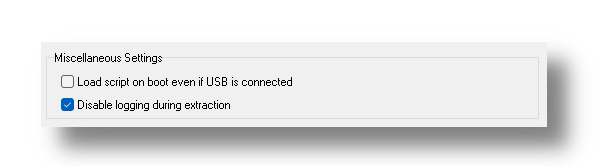
Poorly written embedded coremini scripts may prevent the device from operating properly, or even make it unresponsive. For this reason, A failsafe was implemented to suppress the running of embedded coremini scripts if the device is connected to a computer via USB when the device powers up.
Devices with membrane buttons have an additional failsafe to suppress the running of embedded coremini scripts if held down when the device powers up. These devices have the option to disable the coremini failsafe using USB with the first checkbox below.
For devices with the optional logging capability, the second checkbox disables logging when data is being extracted from the device.
Note
If a device is powered by USB but not connected to a computer, the failsafe will not be triggered and embedded coremini scripts will run as normal. (e.g. if the device is powered with a USB power adapter)
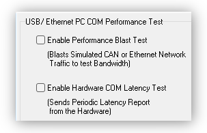
5.15. Performance Tests
The following are tests which can be used to characterize the bandwidth and latency between ICS hardware and its host computer. If problem is encountered with either of these, our Customer Support would be happy to help resolve it. Reference the end of this document for contact information.
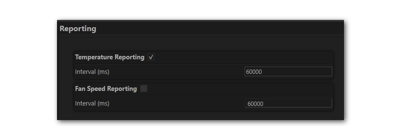
5.16. Reporting
This enables reporting of temperature and fan speed. The reporting interval for each of these can be configured independently.
5.17. ICS Time Sync
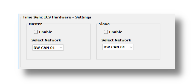
If multiple ICS devices are being used to log networks in parallel, the internal clocks used to timestamp the logged traffic can be synchronized in order to provide time-aligned logs. The following screen is used to configure this clock synchronization.
The devices synchronize using a private CAN network between them. This means no other DUTs or ECUs should be connected to this private CAN network. Each device must be configured from this screen to select which CAN network should be used for synchronization as well as if it is the clock master for all of the loggers or it is a clock slave.
Note
Exactly one device needs to be configured as a clock master when synchronizing clocks between multiple ICS loggers.
Note
This time synchronization is specific to Intrepid devices. If synchronization is required with devices from other manufacturers, gPTP Time Synchronization may be used.