3. A Tour of RAD-IO2 Hardware
The RAD-IO2 system supports several types of isolated I/O modules, each with distinct capabilities:
3.1. RAD-IO2-TC Thermocouple Module
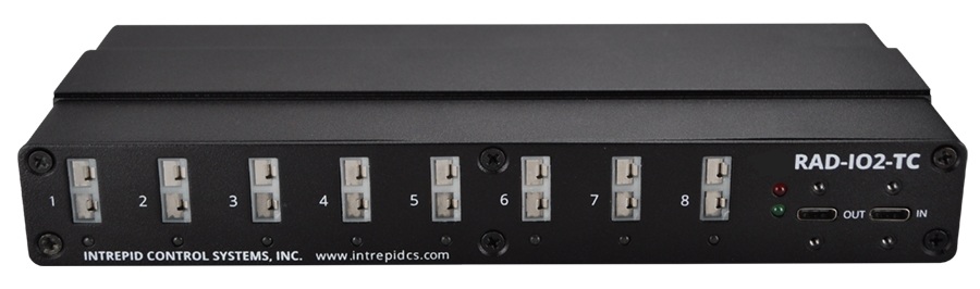
Banks/Channels: 8 independent banks, one K-Type thermocouple channel per bank.
Isolation: Features channel-to-channel isolation without the need for mechanical relays, minimizing settling time and error. Each bank has its own Cold Junction Compensation (CJC) and A/D converter.
Converter: 16-bit Delta Sigma Converter per bank.
Thermocouple Type: K-Type only.
Range & Accuracy:
Range: -270°C to 1260°C
Typical Accuracy: Better than ±1°C (each channel is individually calibrated by Intrepid)
Resolution: 0.2°C
Accuracy: ±2°C (specification)
Noise Rejection: >105 dB Common Mode Rejection at 60 Hz and 50 Hz.
Note: K-Type Thermocouples are not included; purchase separately (e.g., from Omega.com).
3.2. RAD-IO2-AIN Analog Input Module
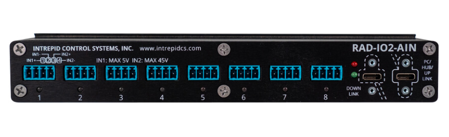
Banks/Channels: 8 independent banks, each with a 16-bit Delta Sigma A/D converter. Functions as 8 independent, “floating” voltmeters.
Ranges (Selectable):
Low Range: ± 250 mV, ± 1000 mV, ± 5000 mV.
High Range: ± 10V, ± 20V, ± 45V.
Caution: Only one range (Low or High) can be used per bank at a time. DO NOT exceed the maximum voltage for the selected range to prevent unit damage.
Resolution: 16-bit. Delta-sigma (ΔΣ) technology provides reduced “jitter” when using slower conversion speeds due to internal sample averaging.
Sampling Rate:
Maximum aggregate across all daisy-chained modules: 1000 samples per second (sps).
Maximum per channel: 100 sps.
Example: 24 channels yield approximately 41 sps (1000/24). One channel yields 100 sps.
Use Case: Suitable for most static or semi-static measurements; too slow for electrical transients, microphones, or accelerometers.
3.3. RAD-IO2-AOUT- Analog Output Module
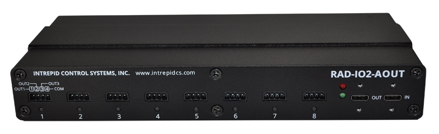
Banks/Outputs: 8 isolated output banks. Total of 24 analog outputs (three 0-5V outputs per bank, with one common ground line per bank).
Converter: 16-bit Digital-to-Analog Converter (DAC).
Resolution: 76.3 µV per bit.
Current Output: 5mA maximum output current per channel (limited by the drive chip).
Power: Approximate current draw if all channels output maximum current: 370mA.
Update Rate: Subject to the same 100 samples per second limitation as the AIN module when updating the analog signal output.
3.4. RAD-IO2-PWRRLY Power Relay module
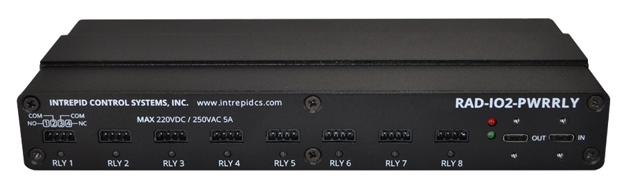
Relays: 8 isolated Form C relays. Each has normally open (NO) and normally closed (NC) connections. The two common connections (pin 2 and pin 3) are internally tied together.
Switching Capacity:
Current: 5A (for DC up to 220VDC) and 5A (for 250VAC).
Power: 60W / 62.5VA.
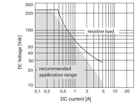
Max DC Load Breaking Capacity specified.
Contact Specifications:
Material: AgNi (Silver and Nickel), gold plated.
Initial Contact Resistance: <50mΩ at 10mA/30mV.
Durability:
High mechanical shock resistance (up to 50g functional).
Electrical Endurance:
(≤30mV/≤10mA): min. 2.5 million operations.
Cable load open end: min. 2 million operations.
Resistive, 220 VDC / 0.27A - 60W: min. 500k operations.
3.5. RAD-IO2-DIO Digital In/Out module
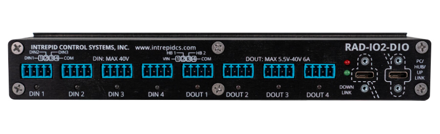
Structure: 8 isolated banks with one common ground per bank.
First 4 banks are inputs (12 total inputs).
Second 4 banks are outputs (8 total outputs).
All banks are mutually isolated.
Digital Inputs (4 Banks / 12 Total)
Input Type: Three 0-40V, 12-bit Analog-to-Digital Converter (ADC) inputs per bank.
Configurable Modes (reconfigurable during operation):
0-40 VDC Analog Input: Reports an analog value.
Digital Input: Reports a digital (0 or 1) value based on a programmable 160mV step threshold.
PWM Input: Reports a digital (0 or 1) value based on a programmable 160mV step voltage threshold.
Period Measurement
Frequency Measurement
Digital Outputs (4 Banks / 8 Total)
Output Type: Each of the 4 isolated output banks has two digital outputs.
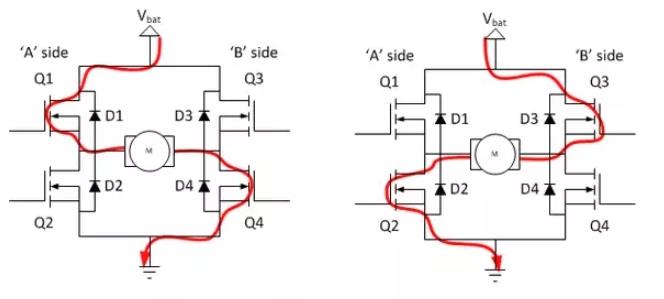
Configuration: Can be configured as separate digital channels (Half Bridge) or combined as a Full H-Bridge output. Four pairs total (8 channels).
Power: Each output can pass 5.5V to 40V at 6A (user-supplied). Uses one BTN8962TA chip per output.
Programmable Modes:
Simple Digital Output
One Shot Output
PWM and frequency programmable output
Half Bridge Mode (when channels are separate)
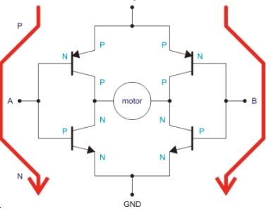
FULL BRIDGE MODE (when channels are joined)