3. A Tour of RAD-Galaxy 2 Hardware
Before learning how to configure and set up the device, let’s examine the device from all sides to understand all of its interfaces and status indicators.
Warning
The RAD-Galaxy 2 is a complex device that does not contain any user-serviceable parts. Do not attempt to open the case of the RAD-Galaxy 2 unless specifically instructed to do so by an Intrepid Control Systems technician, or you risk possible injury or damage to the unit.
3.1. Front Panel Buttons and LED Indicators
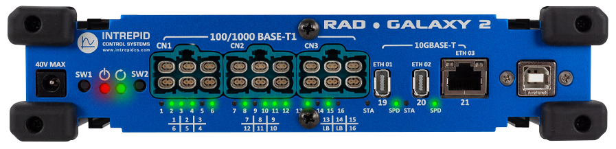
RAD-Galaxy 2 Front View
3.1.1. Device Status LEDs
Bootloader
If the  LED flashes red (with no alternating color), this indicates
the RAD-Galaxy 2 is updating its firmware or in bootloader mode waiting to
update firmware by connecting to Vehicle Spy or neoVI Explorer.
LED flashes red (with no alternating color), this indicates
the RAD-Galaxy 2 is updating its firmware or in bootloader mode waiting to
update firmware by connecting to Vehicle Spy or neoVI Explorer.
|
|
|
|---|---|---|
Firmware Flashing |
Red Flash |
Red Flash |
Device in bootloader |
Green Flash |
Red Flash |
Device Unpowered |
off |
off |
Safe removal of power in bootloader mode
If the device is in bootloader mode, power should not be removed until both LEDs on ETH03 are inactive. Active LEDs on ETH03 indicate that there is a device initialization that must not be interrupted by removing power. Removing power during this initialization will cause the RAD-Galaxy 2 to malfunction until it is placed back in bootloader mode using the front panel buttons and the initialization is allowed to complete successfully.
If the LED in inactive, or
flashes colors other than red, then the following tables define
the LED indications.
 Operating Mode
VSPY Connection |
Coremini |
||
|---|---|---|---|
Green |
Slow Flash (1Hz) |
Offline |
Not Running |
Fast Flash (2.5Hz) |
Connected |
||
Orange |
Fast Flash (2.5Hz) |
Offline |
Running |
Green/Orange (alternating) |
Fast Flash (2.5Hz) |
Connected |
|
Off |
Device Unpowered |
||
Red Flash |
|||
CAN/LIN Status
Activity |
Error Indication |
|
Green Flash |
CAN TX |
Red Flash following a Green or Orange Flash |
Orange Flash |
CAN RX |
|
Green/Orange (Alternating) |
CAN TX and RX |
|
Red Flash Only |
||
3.1.2. CN1/CN2/CN3 Status LEDs
The green LEDs directly below the three H-MTD Connectors (CN1/CN2/CN3) indicates the link status and activity of the 100/1000BASE-T1 ports 1-16. The following table describes their behavior.
Off |
Link Down |
Solid Green |
Link Up |
Flashing Green |
Link Up with RX/TX Activity |
3.1.3. ETH01/02/03 LEDs
Each 10GBASE-T port has two status LEDs
STA (Status)
Off |
Link Down |
Flashing Green |
RX/TX Activity |
SPD (Speed)
If the link is active, the link speed is indicated as follows.
Off |
Link Down |
1 Flash |
Linked at 10Mbps |
2 Flashes |
Linked at 100Mbps |
3 Flashes |
Linked at 1Gbps |
TBD |
Linked at 2.5Gbps |
TBD |
Linked at 5Gbps |
4 Flashes |
Linked at 10Gbps |
3.3. Connector Interfaces
3.3.1. Barrel Jack
The RAD-Galaxy 2 is powered using the barrel jack on the left of the front panel. Power requirements can be found Device Power
3.3.2. USB Type B
This connection is reserved for internal and future use.
3.3.3. Ethernet Ports
ETH01 (RJ-45)
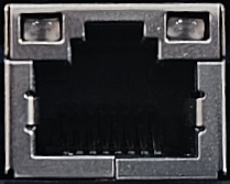
ETH01 is the primary interface to a host PC when using Vehicle Spy or Intrepid’s Open Source API
ETH01/ETH02 (IX Connectors)
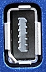
ETH01 and ETH02 use the industrial IX connector and have multiple uses depending on the RAD-Galaxy 2 configuration.
Alternate computer connection
Streaming CMP traffic to a PC or data logger
A MultiG active tap pair
In many cases, an IX to RJ45 cable is required to connect these ports to office or lab computers. They are widely available through distributors or can be at the links given in this section
AE01-AE16 (H-MTD)
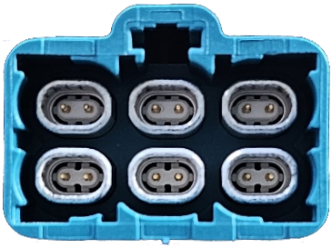
The three H-MTD connectors contain ports AE01-AE16, which are the 100/1000BASE-T1 ports that can be used in an active tap configuration or independently. Details on this configuration can be found in this section
The mating connector for CN1-3 is Rosenberger part number E6K10F-1CAZ5-Y. Information on premade harnesses can also be found this section
The cavity assignment of each connector are as follows (as seen looking into the connectors of the RAD-Galaxy2)
CN1 
CN2 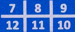
CN3 
Loop Back Ports
Note the 2 cavities on CN3 labeled “LB” are a loop back connection. These ports are connected internally and are intended as a convenient way to bypass an active tap for debugging purposes.
3.3.4. HD-26 Conventional Network Interface Connector (CAN/MISC)
This male, high-density, 26-pin D-subminiature connector contains the CAN and LIN networks, as well as the miscellaneous I/O
Device Power
Unlike many Intrepid products, the RAD-Galaxy 2 cannot be powered using the DB-26.
Pin # |
Name |
Description |
1 |
MISC 1 |
Miscellaneous: DI/O (0–3.3V) |
2 |
DW CAN 4 L |
HS CAN 4 Low |
3 |
DW CAN 5 L |
HS CAN 5 Low |
4 |
DW CAN 1 L |
HS CAN 1 Low |
5 |
DW CAN 8 L |
HS CAN 8 Low |
6 |
DW CAN 2 L |
HS CAN 2 Low |
7 |
DW CAN 3 L |
HS CAN 3 Low |
8 |
DW CAN 6 L |
HS CAN 6 Low |
9 |
MISC 2 |
Miscellaneous 2: Enhanced miscellaneous I/O (analog or digital with PWM and 0–40V support) AI/O + DI/O |
10 |
GND |
Ground |
11 |
MISC 3 |
Miscellaneous 3: DI/O (0–3.3V) |
12 |
DW CAN 4 H |
HS CAN 4 High |
13 |
DW CAN 5 H |
HS CAN 5 High |
14 |
DW CAN 1 H |
HS CAN 1 High |
15 |
DW CAN 8 H |
HS CAN 8 High |
16 |
DW CAN 2 H |
HS CAN 2 High |
17 |
DW CAN 3 H |
HS CAN 3 High |
18 |
DW CAN 6 H |
HS CAN 6 High |
19 |
N/C |
N/C |
20 |
MISC 4 |
Miscellaneous 4: DI/O (0–3.3V) |
21 |
DW CAN 7 L |
HS CAN 7 Low |
22 |
LIN 01 / ISO K 01 |
LIN Channel 1 |
23 |
LIN 02 |
LIN Channel 2 |
24 |
EXT WAKE |
External Wake |
25 |
ETH 01 ACTIVATE |
Ethernet Activation Line |
26 |
DW CAN 7 H |
HS CAN 7 High |
AIN 1/AIN 2 - Differential Analog Input
The RAD-Galaxy 2 measures the differential voltage between AIN1 (upper voltage) and AIN2 (lower voltage). If a differential measurement is not needed, AIN2 must be grounded for proper operation. This input is mutually exclusive with the PWMIO.
AIN 1 (Differential +) |
0V - 40V |
AIN 2 (Differential -) |
0V - (<AIN1) |
Resolution |
24.4 mV |
Sampling Rate |
~1kHz |
Supported Vehicle Spy Function Block Operations |
GetVal Analog Input Value |
Warning
Under all circumstances, AIN2 must be at a lower voltage than AIN1. Failing to meet this requirements will result in malfunction and possibly permanent damage to the RAD-Galaxy 2.
AOUT 1: Analog Output
RAD-Galaxy 2 has a single analog output with the following specifications.
Output Voltage Range |
0-5V |
Output Resolution |
1.22 mV |
Max Output Current |
30mA |
Slew Rate |
1.8V/µS |
Supported Vehicle Spy Function Block Operations |
SetVal Analog Output Value |
GetVal Analog Output Value |
PWMIO: PWM Input
The RAD-Galaxy 2 has 2 PWM Inputs with the following specifications. These inputs are mutually exclusive with the Analog Input and PWM Outputs.
Logic Threshold |
~3.3V |
Max Frequency |
5 kHz |
Frequency Resolution |
0.1 Hz |
Duty Cycle Resolution |
0.10% |
Supported Vehicle Spy Function Block Operations |
Set PWM Output Value |
Set PWM Output Frequency |
|
Set PWM Output Duty Cycle |
|
Get PWM Output Value |
|
Get PWM Output Frequency |
|
Get PWM Output Duty Cycle |
|
Get PWM Output Period |
|
Set IO “state” |
|
Set IO “output/direction” |
PWM Outputs
The RAD-Galaxy 2 has 2 PWM Outputs with the following specifications. These inputs are mutually exclusive with the Analog Input and PWM Inputs.
V High (min) |
TBD |
Max Current |
TBD |
Max Frequency |
5 kHz |
Duty Cycle Resolution |
0.1 Hz |
Supported Vehicle Spy Function Block Operations |
Set PWM Output Value |
Set PWM Output Frequency |
|
Set PWM Output Duty Cycle |
|
Get PWM Output Value |
|
Get PWM Output Frequency |
|
Get PWM Output Duty Cycle |
|
Get PWM Output Period |
|
Set IO “state” |
|
Set IO “output/direction” |