2. Introduction and Overview
2.1. Introduction
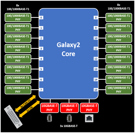
Thank you for purchasing an Intrepid Control Systems RAD-Galaxy 2, a 16-port 100/1000BASE-T1 active tap. The 16 ports can be configured as 8 active taps to monitor communications between 8x 100/1000BASE-T1 Ethernet nodes and a switch or between 8 pairs of nodes. They can also be configured to be used as 16 independent ports connecting Automotive Ethernet devices to a PC, test equipment, or data logger.
In addition to its powerful Automotive Ethernet capabilities, the RAD-Galaxy 2 contains 8x CAN FD ports and 2x LIN ports.
2.2. Package Contents
Upon receipt, please remove, unwrap and inspect all its contents. If anything is missing or damaged, please contact Intrepid for prompt assistance using the Customer Support information at the end of this guide.
2.2.1. Hardware
Your RAD-Galaxy 2 package includes the following:
The RAD-Galaxy 2 device
1x standard RJ45 Ethernet cable (CAT6)
A 12 Volt Power Supply
If purchased, the following accessories may also be present.
2.2.2. Software
Unless physical media was specifically requested, your box should contain a reference card with instructions on where to download the device drivers and any other purchased software. If your media or reference card cannot be located, please contact Customer Support.
2.3. Device Overview
The RAD-Galaxy 2 contains a number of different network interfaces and features to allow it to support a wide variety of use cases. While the primary function of the RAD-Galaxy 2 is an active tap, it can also be used to create gateways, and connect a PC to an array of ECUs in parallel for simulation, testing, or even reflashing.
2.3.1. Block Diagram
2.3.2. Network Interfaces
- 16x 100/1000 BASE-T1 Automotive Ethernet PHYs.
Switchable between 8 active taps or 16 independent ports
Automatic or static master/slave PHY configuration
LED indicators for Link Status and Network Activity
Full-duplex support for simultaneous data transmission and reception across all PHYs.
TC10 Automotive Ethernet Sleep/Wake Functionality
Automotive MACsec Capable
3x 10GBASE-T 10/100/1000 Gigabit Ethernet PHYs
8x CAN FD Channels with software-programmable termination.
2x LIN channels
2.3.3. Product Features
- Standalone Modes
Embedded Script Execution
High-performance Gateways
Low-power modes
64-bit timestamping with 10 ns accuracy on all Ethernet, CAN and LIN networks
Battery-backed real time clock (RTC)
Field-upgradeable firmware
1x Analog Out channel TODO
1x differential Analog In channel or 2x GPIO/PWM channels TODO
Rugged aluminum enclosure with rubber bumpers for durability
1 Year Limited Warranty
2.3.4. Electrical and Mechanical Characteristics
Device Power 10-40V
Temperature Range: -40°C to +80°C
Product Dimensions: 7.375” x 8.75” x 2”
Product Weight: Approx. 3 lbs.
H-MTD connection systems for 1000BASE-T1 Ethernet connections
2.4. Operational Overview and Use Cases
The following section will outline some of the more common use cases, however it should not be interpreted as a complete list of the device’s full capabilities.
The RAD-Galaxy 2 has a multitude of capabilities and can perform a number of different functions, many of them simultaneously. The Automotive Ethernet ports can be configured as active taps or independent ports. At the same time it can also act as an interface to conventional vehicle networks such as CAN and CAN FD, with support for LIN and analog or PWM I/O lines.
2.4.1. Operation as an Active Tap
Due to the full duplex nature of 100/1000BASE-T1, typical approaches for interfacing to a network (such as attaching a probe to the bus) do not work. This problem is resolved by inserting a device called an active tap within an Automotive Ethernet network.
The RAD-Galaxy 2 contains 16x 100/1000BASE-T1 transceiver chips (PHYs) that can be configured as independent ports or up to 8 tap pairs. These tap pairs can be interposed between two Automotive Ethernet devices to monitor network traffic between them, as well as inject traffic. ETH 03, a 10G Ethernet ports is used to connect the RAD-Galaxy 2 to a laptop for use with Vehicle Spy software, Intrepid’s Open Source API , as well as configuration and firmware updates.
Note
The term “tap” has a dual meaning: it refers to the act of tapping into a network (such as used in the phrase “wire tap”). It also is sometimes considered an acronym for “test access point”, since a tap does indeed act as an access point for testing, though you can do much more than that with the RAD-Galaxy 2. For simplicity, in this document we will just use the word “tap”.
Once configuration is complete, the RAD-Galaxy 2 is set up as a “middle man” in the network, When a node or switch port transmits, the RAD-Galaxy 2 receives the message and retransmits it to the device connected to that tap pair, with only a minor delay for processing. The processor also sends a copy of the message over the 10G Ethernet connection to the PC, so it can be viewed and analyzed within Vehicle Spy.
The interface provided by the RAD-Galaxy 2 is full-duplex and bidirectional. This means that in addition to using the PC to monitor messages sent by the Automotive Ethernet nodes attached to it, you can create and send custom messages from the PC to the nodes as well. This allows you to query, test, configure and manage these nodes using Vehicle Spy.
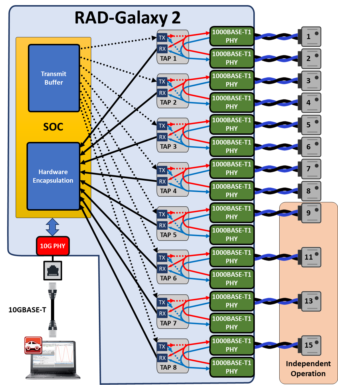
The following figure depicts how the RAD-Galaxy 2 functions when inserted into a typical Automotive Ethernet network with 8 AE nodes connected to a Zonal Aggregator Module. (or a switch)
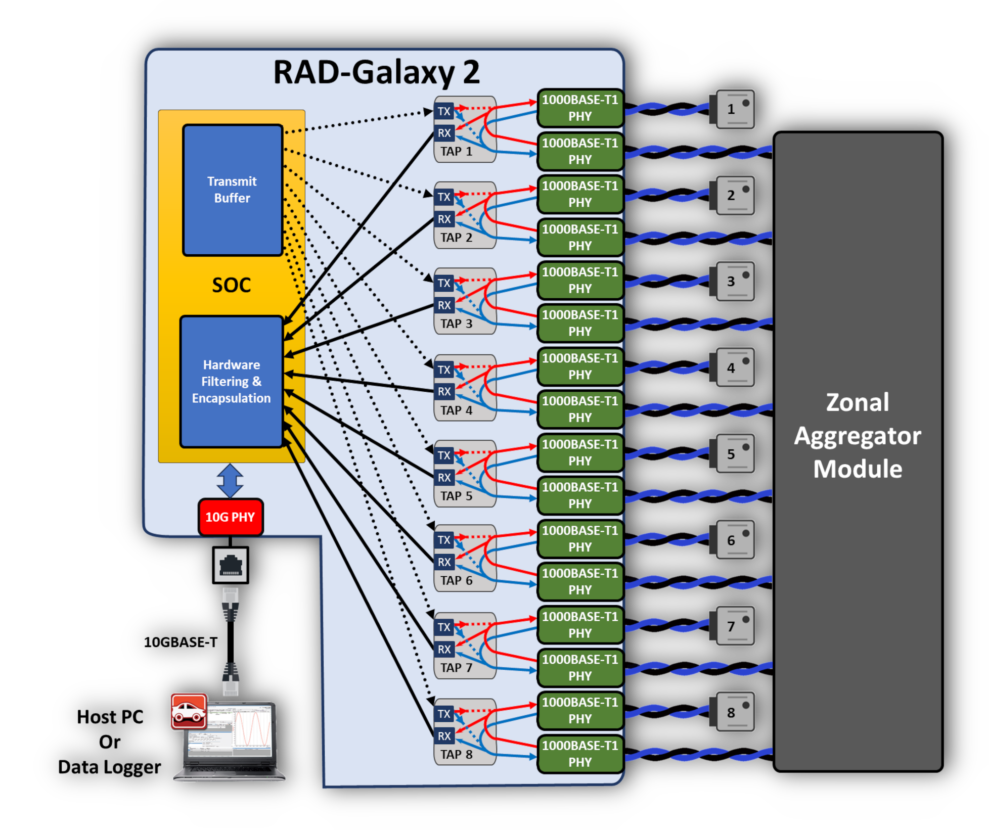
Using the RAD-Galaxy 2 as an Active Tap Between AE Nodes and Switch. Before inserting the RAD-Galaxy 2, Automotive Ethernet nodes 1 to 8 were directly connected to the switch on the right. Each connection was broken and the pairs connected to the appropriate ports on the RAD-Galaxy 2. Every transmission continues to be sent to its prior destination (note the loops inside the taps connecting the nodes). In addition, copies of each message are transmitted by the RAD-Galaxy 2 to the attached PC. (note the arrows inside the taps connecting the loops and the RX buffer.) Optionally, messages from the PC may also be sent to any switch port or ECU (dashed lines).
The following figure shows a similar setup, except with the RAD-Galaxy 2 interposed between 8 pairs of Automotive Ethernet nodes, rather than between nodes and a switch.
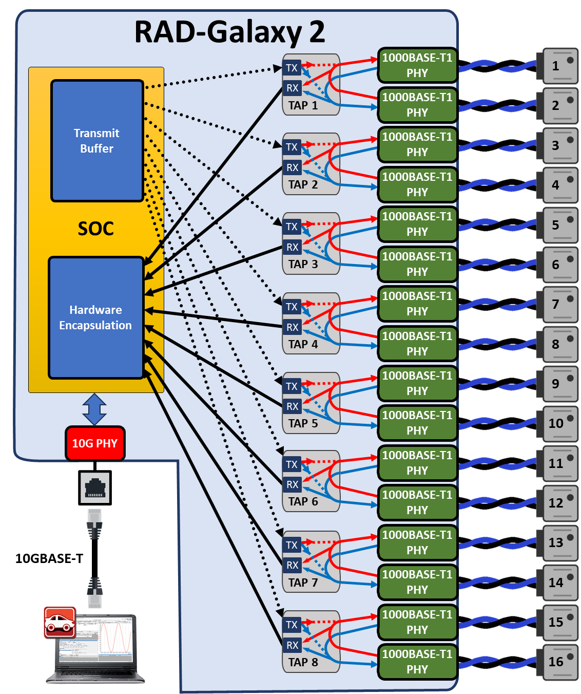
Using the RAD-Galaxy 2 as an Active Tap Between AE Node Pairs. In this application, 16 nodes were formerly connected to each other in pairs: Node 1 to Node 2, Node 3 to Node 4, and so on. The RAD-Galaxy 2 has been inserted between each pair, keeping the communication path intact while allowing all traffic to be monitored by the PC, and additionally messages from the PC can be sent to the nodes.
2.4.2. Independent Port Operation
Instead of being placed between Automotive Ethernet devices, the RAD-Galaxy 2 can be configured to interface to 16 nodes independently. Any traffic received by a node will be converted from Automotive Ethernet to standard Ethernet and sent to the PC. Conversely, traffic from the PC will be converted from standard Ethernet to Automotive Ethernet and sent to the appropriate node. This is often used to test ECUs in parallel or “Gang Flash” ECUs in parallel.
Using the RAD-Galaxy 2 configured for independent ports. The RAD-Galaxy 2 allows a PC to interact with up to 16 Automotive Ethernet nodes. Each node can send to the PC, and vice-versa, simultaneously.
2.4.3. Mixed Topology Operation
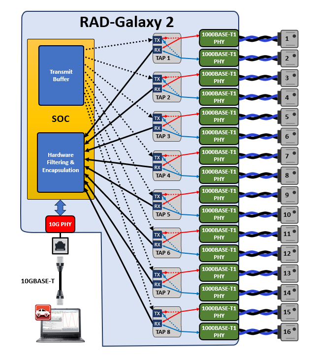
If the RAD-Galaxy 2 is in active tap configuration, it is possible to connect a node to only one of the two connections of any of its six pairs. With only one device in the pair, the node will only be able to send and receive to and from the PC, effectively operating as an independent port. This allows you to “mix and match” how you use the 6 pairs in the device: for example, you can use 5 pairs as active taps, and attach an addition device to the 6th pair by itself for use as a media converter. This is depicted in Figure 5, which is just a slight variation on Figure 3.
Any combination of 6 active taps and 6 media converter connections is possible in this manner. If you want to use the RAD-Galaxy 2 as a media converter for more than 6 devices you must set it into media converter mode as described earlier, which precludes using it as an active tap at the same time.
Using the RAD-Galaxy 2 as Both an Active Tap with independent ports. In this variation on the configuration shown earlier, we have removed AE Nodes 10, 12, 14, and 16. This leaves Nodes 9, 11, 13, and 15 as the only Nodes on a tap pair, so it only communicates with the PC, effectively now operating as if connected to an independent port. Meanwhile Nodes 1+2, 3+4, 5+6, and 7+8 remain in pairs functioning in active tap mode.
2.4.4. Timestamping and Frame Wrapping
The RAD-Galaxy 2 records the time that each message is received on any of its Automotive Ethernet ports. This hardware-level timestamp is then transmitted in a special wrapper frame over its conventional Ethernet links, encapsulating the original message. The wrapper frame contains its own Ethernet header and Frame Check Sequence (FCS) field, along with an extra header containing information specific to the RAD-Galaxy 2. Detail on the time stamping can be found in this section of the guide Ethernet Hardware Time Stamping
Ethernet controllers normally discard any frames received for which an error has been detected, and strip the FCS error-detection field even on valid frames. The RAD-Galaxy 2’s special wrapping mechanism allows it to capture Ethernet frames in their entirety, including the FCS field, and ensures that error frames are preserved so they can be analyzed.
2.4.5. CAN FD and LIN Networks
In addition to its Automotive Ethernet capabilities, the RAD-Galaxy can act as an interface to conventional vehicle networks. It includes hardware for 8 CAN FD channels. All channels are captured simultaneously, and are hardware time-stamped with great accuracy. Non-Ethernet messages are encapsulated into Ethernet frames and transmitted to the PC over the same Ethernet connection used for Automotive Ethernet data, where they are decoded and displayed by Vehicle Spy. The RAD-Galaxy also has hardware support for two LIN Channels.
2.4.6. Simulation and Scripting
Using Vehicle Spy you can define transmit messages on any network with custom data and send them manually or on a schedule of your choosing. You can also write intelligent scripts that implement arbitrary logic and compile them into embedded scripts which can run within the device itself. This functionality allows you to create specialized test scenarios, and to simulate ECUs and gateways.
2.4.7. PHY Register access
In any mode, each PHY can be accessed by the embedded processor over MDIO in order to read and write configurations registers. More information can be found in Device Register Access
2.5. Hardware Requirements
2.5.1. Device Power
The RAD-Galaxy 2 requires a DC supply between 10V-40V that provides 60 watts or more. It draws a nominal current of 5A at 12V. The power is connected to the barrel jack on the left side of the front panel.
2.5.2. Computer Interface
Connecting ETH03 to a computer is needed both for configuration of the tool as well as to communicate with the device if you intend to use Vehicle Spy or Intrepid’s available API.
As a hardware device, there are no specific requirements on the computer aside from having a standard Ethernet port and the proper device driver installed. (See Software Setup for more detail)
IT Policies
With IT security a growing concern, many IT departments block certain types of Ethernet traffic and communication. In some cases, this has been found to interfere with Intrepid devices connected to a host computer using Ethernet. If you find you are having trouble please contact our Customer Support.
Host Connection
Note that while the RAD-Galaxy 2 will connect to a host computer at speeds as low as 100Mbps, it was designed to link at 10G to support the aggregated traffic of all of its Ethernet ports.