8. Advanced Features
8.1. MACsec
MACsec (802.1AE) is a Layer 2 protocol that can ensure data integrity and authenticity, as well as data encryption. The OPEN Alliance TC17 has drafted the MACsec Automotive Profile to adapt the broad standards of 802.1AE to automotive applications.
The use and operation of MACsec is well beyond the scope of this guide, but many Intrepid products contain Automotive Ethernet PHYs with MACsec support. This guide explains the different way of loading MACsec configurations and keys into the Automotive Ethernet PHY.
8.1.1. Intrepid Devices Supporting MACsec
The MACsec configuration of a PHY is contained in a yaml file that is sent to the PHY Using Vehicle Spy or one of Intrepid’s API. (Examples follow) The following table contains the information needed to address the PHY using the API.
Product |
Serial # |
Port |
netid |
config_netid |
RAD-Moon2_zl |
RNxxxx |
100/1000BASE-T1 |
NETID_OP_ETHERNET1 |
NETID_MDIO_01 |
RAD-Moon3 |
R3xxxx |
100/1000BASE-T1 |
NETID_OP_ETHERNET1 |
NETID_MDIO_01 |
RAD-Comet2 |
RCxxxx |
AE01 |
NETID_OP_ETHERNET1 |
NETID_MDIO_02 |
RAD-Gigastar |
GSxxxx |
SFP1 |
NETID_ETHERNET |
NETID_I2C1 |
SFP2 |
NETID_ETHERNET2 |
NETID_I2C2 |
||
RAD-Gigastar2 |
GTxxxx |
AE01 |
NETID_OP_ETHERNET1 |
NETID_MDIO_01 |
AE02 |
NETID_OP_ETHERNET2 |
NETID_MDIO_02 |
||
SFP1 |
NETID_ETHERNET |
NETID_I2C1 |
||
SFP2 |
NETID_ETHERNET2 |
NETID_I2C2 |
||
RAD-Galaxy2 |
G2xxxx |
AE01 |
NETID_OP_ETHERNET1 |
NETID_MDIO_01 |
AE02 |
NETID_OP_ETHERNET2 |
|||
AE03 |
NETID_OP_ETHERNET3 |
|||
AE04 |
NETID_OP_ETHERNET4 |
|||
AE05 |
NETID_OP_ETHERNET5 |
|||
AE06 |
NETID_OP_ETHERNET6 |
|||
AE07 |
NETID_OP_ETHERNET7 |
|||
AE08 |
NETID_OP_ETHERNET8 |
|||
AE09 |
NETID_OP_ETHERNET9 |
NETID_MDIO_02 |
||
AE10 |
NETID_OP_ETHERNET10 |
|||
AE11 |
NETID_OP_ETHERNET11 |
|||
AE12 |
NETID_OP_ETHERNET12 |
|||
AE13 |
NETID_OP_ETHERNET13 |
|||
AE14 |
NETID_OP_ETHERNET14 |
|||
AE15 |
NETID_OP_ETHERNET15 |
|||
AE16 |
NETID_OP_ETHERNET16 |
8.1.2. Configuring MACsec in Vehicle Spy 3
In Development
8.1.3. Configuring MACsec using Intrepid’s Open Source API
libicsneo is the Intrepid Control Systems device communication library.
Installation and usage documentation can be found within each of the respective APIs.
MACsec C++ API
Coming Soon!
MACsec Python API
Coming Soon!
MACsec C API
Coming Soon!
8.1.4. Configuring MACsec in using python_ics
Python Installation
pip install python_ics pyyaml
Usage
ics_load_macsec.py [-h] [--yaml YAML] --port PORT [--reset] serial_number
serial_number
The serial number of the device to configure.
options
Option |
Descrition |
Default Value |
-h, –help |
show this help message and exit |
|
–yaml YAML |
filename of yaml configuration to be loaded (Assumes .yml is located in “/yaml/” directory) |
test_macsec_Rule_wildcard_SecY_128_strip_strict_sci_SA_sak0.yml |
–port PORT |
‘config_netid’ - network ID for the port configuration network. |
config_netid = NETID_I2C2 |
‘netid’ - network ID for the port network. |
netid = NETID_OP_ETHERNET1 |
|
–reset |
Reset and clear and disable MACsec on the device, then exit; yaml configuration ignored |
FALSE |
Example Command Lines
RAD-Comet2/3:
python ics_load_macsec.py Rxxxxx --port "{'netid':NETID_OP_ETHERNET1,'config_netid':NETID_MDIO_02}" --yaml "test_sfp_macsec_Rule_wildcard_SecY_128_strip_strict_sci_SA_sak0.yml"
RAD-Moon2_zl:
python ics_load_macsec.py RNxxxx --port "{'netid':NETID_OP_ETHERNET1,'config_netid':NETID_MDIO_01}" --yaml "test_sfp_macsec_Rule_wildcard_SecY_128_strip_strict_sci_SA_sak0.yml"
RAD-Moon3:
python ics_load_macsec.py R3xxxx --port "{'netid':NETID_OP_ETHERNET1,'config_netid':NETID_MDIO_01}" --yaml "test_sfp_macsec_Rule_wildcard_SecY_128_strip_strict_sci_SA_sak0.yml"
RAD-Gigastar Port1 with SFP-MV2221M:
python ics_load_macsec.py GSxxxx --port "{'netid':NETID_ETHERNET,'config_netid':NETID_I2C2}" --yaml "test_sfp_macsec_Rule_wildcard_SecY_128_strip_strict_sci_SA_sak0.yml"
RAD-Gigastar Port2 with SFP-MV2221M:
python ics_load_macsec.py GSxxxx --port "{'netid':NETID_ETHERNET2,'config_netid':NETID_I2C3}" --yaml "test_sfp_macsec_Rule_wildcard_SecY_128_strip_strict_sci_SA_sak0.yml"
8.2. Hardware RX Message Filters
With 8 Active Taps having an aggregate bandwidth of 16 Gbps, the RAD-Galaxy 2 can send more network traffic than most PCs can handle and rapidly fill all but the highest capacity data loggers. Since many use cases only involve looking at a fraction of the network traffic in the vehicle, the RAD-Galaxy 2 is equipped with hardware filtering that can restrict the messages sent to the host computer or data logger based on rules created in Vehicle Spy’s message editor interface.
8.2.1. Filter Rules
The RAD Galaxy2 supports up to 31 filtering rules to restrict the traffic sent to the host computer or data logger.
Rules are based on a bit-mask that is applied to the first 96 bytes of each frame received by the RAD-Galaxy2
It is a ternary bit-mask, meaning it can contain bit-wise wildcards.
Any frame matching a mask is received by the host PC or Data logger
Any frame that does not match a mask is not received by the host PC or data logger
All frames pass through an active tap regardless of RX Message Filter configuration
This means that frames can be filtered based on any arbitrary bit pattern from the MAC Addresses to an IP socket address and every piece of header information in between.
Current Hardware RX Filter Limitations
There are some limitations in early releases of RAD-Galaxy2 firmware.
Rules are applied to all Ethernet ports. In a future release, selectively applying the rules to Ethernet ports will be possible.
Rules are strictly inclusive and all frames not matching are blocked. In a future release, exclusive rules will be possible.
8.2.2. Creating a Filter
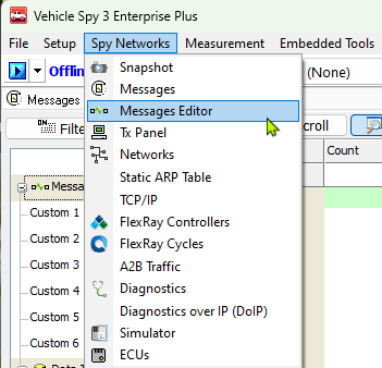
To create a message filter, first open the message editor in Vehicle Spy using the following menu.
Creating a TCP Filter
Once the message editor is open, use the following diagram to follow the numbered steps in creating a TCP message filter.

 Press the Receive button to open the RX filter interface.
 Select the Ethernet port the filter applies to.
 Press the “+” button to create a new message.
Note
Note: In many cases, the header information of the filter can be changed in 2 locations in the message editor as indicated by the arrows.
 The name of the filter can be set.
 Ethertype of the message filter
 VLAN target
 Protocol: For IPv4 and IPv6, this is the layer 4 protocol. For other Ethertypes, this field can represent different header information such as the subtype of an IEEE 1722 or gPTP message
 Source IP Address: Note that a specific IP address is shown, but a range of IP addresses can be set by using an “X” (wildcard) in any one of the 4 bytes.
 Source Port: Note that a specific port is chosen, but this could also be a wildcard (“X”).
 Destination IP Address: 4 wildcards will match any IP address in this example
 Destination Port: A wildcard will match any port.
Creating an IEEE 1722 Filter

Press the Receive button to open the RX filter interface.
Select the Ethernet port the filter applies to.
Press the “+” button to create a new message.
Note
Note: In many cases, the header information of the filter can be changed in 2 locations in the message editor as indicated by the arrows.
The name of the filter can be set.
Ethertype of the message filter
VLAN tag
Protocol: For IEEE 1722, this field represents the stream subtype. Note that
this is an example of a field that can only be edited in one location.
Source MAC Address: Note that a specific IP address is shown, but
a range of IP addresses can be set by using an “X” (wildcard) in any one of the 4 bytes.
Destination MAC Address:
8.2.3. Enabling the Hardware Filters
Once hardware filters have been defined in the message editor, they need to be activated in the hardware. This requires two things to be completed.
Enable the messages in a Function Block
This is required to specify to the hardware which filters should be activated.
The interface to create Function Blocks is found in the Vehicle Spy Scripting and Automation Menu.
From the Function Blocks view, create a Script Type Function Block. If you are unfamiliar with this interface, a full overview can be found in the VSPY Documentation .
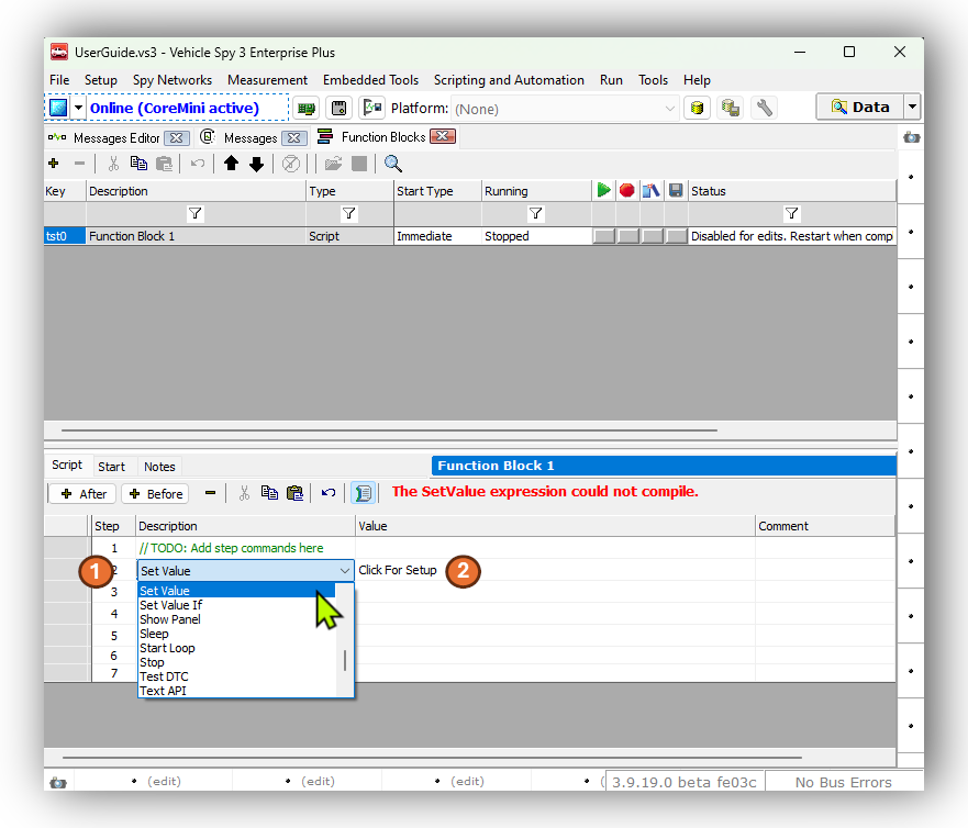
Once you have created your Script Type Function Block, on an empty line, select a “Set Value” statement
Open the Expression Builder by double clicking the field containing “Click for Setup”
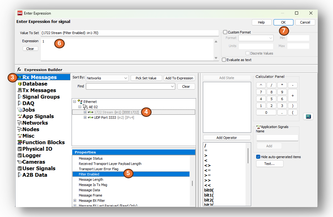
Select “RX Messages” on the left panel of the window.
Select the Ethernet networks where the RX messages were created and select the message filter.
In the Properties window below, double click “Filter Enabled” to add this property to the “Value To Set field at the top”.
Enter a “1” in the Expression field.
Press the OK button
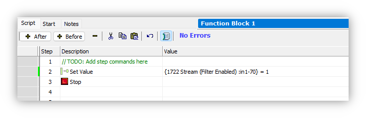
Lastly, complete the Function Block by adding a “Stop” statement.
Send the filters to the hardware using the CoreMini Console
Now that the filters are specified to be activated, they must be sent to the hardware.
The CoreMini Console is found in the Tools menu.
Once opening the CoreMini Console, follow the steps below to send it to the hardware.
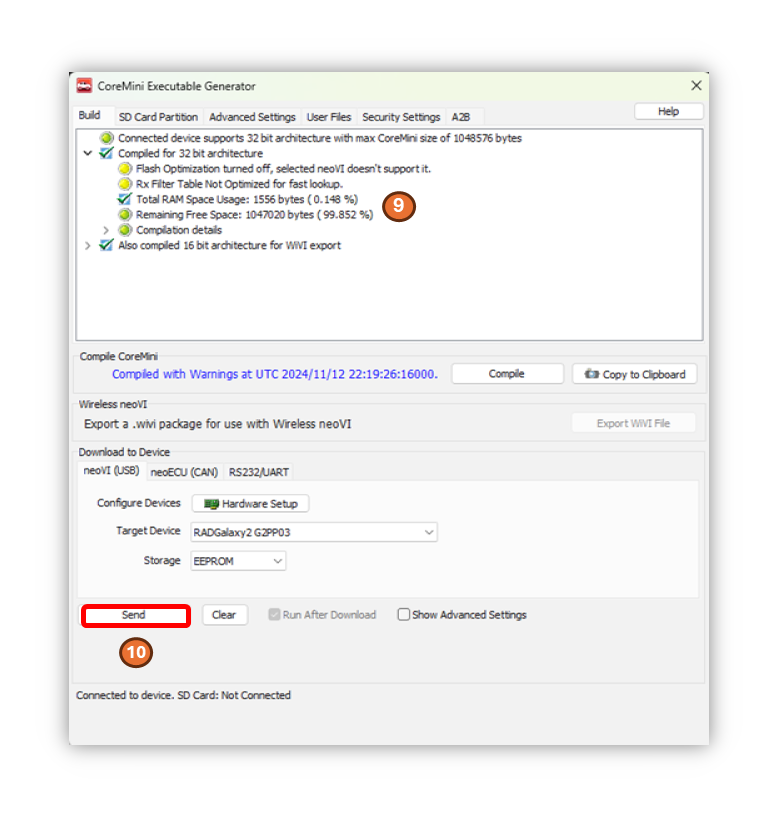
Verify there are no errors in compiling the filters. (most warnings are of no concern)
Press the “Send” button
Rules are Inclusive
When there are no RX Filters loaded, all traffic is forwarded to the host computer or data logger. One or more filters exclude all traffic not matching at least one of the filters loaded in the RAD-Galaxy2.
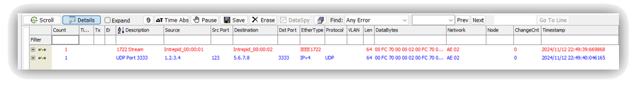
8.2.4. Verifying Filter Operation
After sending the filters to the hardware, the “(CoreMini active)” should be seen when going online with the device as shown below.
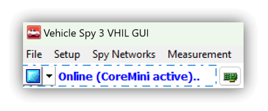
At this point, any message that matches the filters in the hardware will be received and displayed. All other messages will not be seen in VSPY, however they will pass through an active-tap.
If no messages are seen, clear the filters from the hardware. Then go online with VSPY and verify that there are messages received that match the filters created in the Messages Editor. A simple way to verify the filters is to specify a color in the Messages Editor. This will highlight the matching messages by color.
8.2.5. Clearing Filters from Hardware
The filters are deleted in the hardware by opening the CoreMini Console and pressing the “Clear” button.
8.3. Device Register Access
Ethernet PHYs and switches contain many status and configuration registers. The method in which these registers are accessed depend on both the device and decisions made during the electrical design of the product. Intrepid products access PHY and Switch registers either using MDIO or SPI interfaces. The table below lists the Ethernet devices contained in your product along with the management interface information needed to access a device’s registers using Vehicle Spy or Intrepid’s Open Source API.
8.3.1. Ethernet Device Register Interfaces
The MDIO addressing for the Ethernet ports of the RAD-Galaxy2 are as follows.
Port |
MDIO Bus Index |
PHY Address |
Protocol |
|
RAD-Galaxy2 |
AE 01 |
0 |
0 |
Clause 45 |
AE 02 |
1 |
|||
AE 03 |
2 |
|||
AE 04 |
3 |
|||
AE 05 |
4 |
|||
AE 06 |
5 |
|||
AE 07 |
6 |
|||
AE 08 |
7 |
|||
AE 09 |
1 |
0 |
||
AE 10 |
1 |
|||
AE 11 |
2 |
|||
AE 12 |
3 |
|||
AE 13 |
4 |
|||
AE 14 |
5 |
|||
AE 15 |
6 |
|||
AE 16 |
7 |
|||
Ethernet1 |
TBD |
TBD |
||
Ethernet2 |
TBD |
TBD |
||
Ethernet3 |
TBD |
TBD |
8.3.2. MDIO Protocol
This section provides an introduction and overview of the MDIO protocol.
Already familiar with MDIO?
If this information is not needed, skip to the following sections for instruction on how to use this protocol with Vehicle Spy or Intrepid’s Open Source API.
Each MDIO frame is 32 bits:
2 start bits
2 bit operation code
5 bit phy address
5 bit register address
2 bit turn around delay
16 bits of data.
As Ethernet devices has evolved over the years, so has the protocol used to communicate with them. Devices in Intrepid products use either Clause 22 or Clause 45, which will be explained in the following sections.
Clause 22
The initial protocol, IEEE 802.3 Clause 22, was designed to read or write 32 registers within 32 devices. Each read/write is done in one operation.
Phy Address 5 bits (0 – 31 decimal)
Register address 5 bits (0 – 31 decimal) or (0 – 1F hex)
Data 16 bits
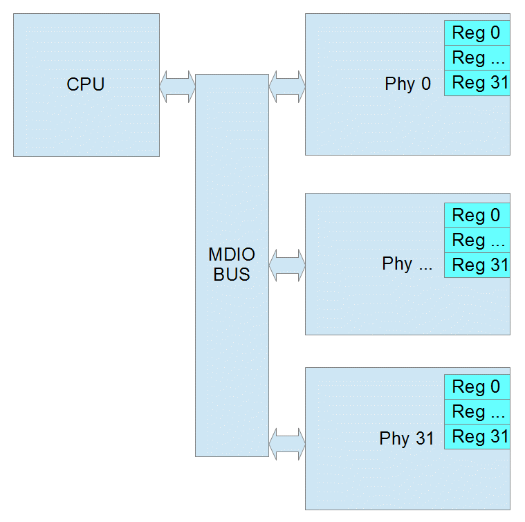
Page Register
Some Ethernet Phy manufacturers added a page register to allow for more registers in Clause 22. The page can be 0 – 255 decimal. If the Phy does not support pages, then page will be ignored. When using pages, reads and writes can no longer be performed in one operation. Instead you must write to the page register and then before any other process changes the page, you can read or write the destination register. If another process were to change the page register before you finish, the result will be an read the wrong register or an write to wrong register which may cause the Phy to stop working.
Common Clause 22 Registers
Clasuse 22 Registers |
Bits |
Function/Status |
|
Control Register (Register 0) |
15 |
reset |
|
14 |
loopback |
||
12 |
auto negotiate |
||
11 |
power down |
||
10 |
isolate |
||
9 |
renegotiate |
||
8 |
duplex |
||
7 |
collision test |
||
6,13 |
speed |
10=1000mbps |
|
01=100mbps |
|||
00=10mbps |
|||
Status Register (Register 1) |
5 |
Auto Negotiation Complete |
|
4 |
Remote Fault |
||
3 |
Auto Negotiation Capability |
||
2 |
Link Status |
||
1 |
Jabber Detect |
||
0 |
Extended Capability |
||
PHY ID Reg 1 (Register 2) |
15:00 |
OUI bits 3:18 | (see figure) |
|
PHY ID Reg 2 (Register 3) |
15:10 |
OUI bits 19:24 | (see figure) |
|
9:04 |
Model Number |
||
3:00 |
Revision Number |
||
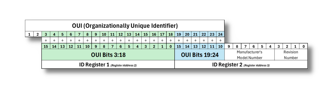
Organizationally Unique Identifier (OUI) Mapping to Clause 22 PHY ID Registers
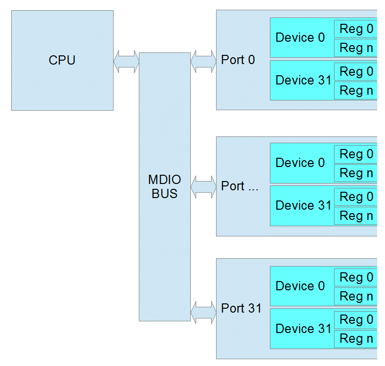
Clause 45
As Ethernet Phys became more complicated and supported different speeds and connections, IEEE 802.3 Clause 45 was added. Because the Register Address is now 16 bits, each read/write takes at 2 operations. The first operation is always writing the Register Address that you want to use in the next operation. The second is the actual read or write. There is also a special read that increments the address after each read which allows you to write a starting address and then read a whole block of registers.
Port 5 bits (this is equivalent to the Phy Address)
Device 5 bits (this is similar to the page)
Register address 16 bits (this allows 65536 registers in each device)
Data 16 bits
Common Clause 45 Registers
Device |
Register |
Bits |
Function/Status |
||
Control Register |
PMA/PMD = 1 PCS = 3 |
0 |
15 |
reset |
|
11 |
power down |
||||
6/13 |
speed (10-1000mbps) |
11=Speed set by bits 5:2 |
|||
10=1000mbps |
|||||
01=100mbps |
|||||
00=10mbps |
|||||
5:2 |
speed (2.5-10 Gbps) |
0111=5 Gbps |
|||
0110=2.5 Gbps |
|||||
0000=10 Gbps |
|||||
Device ID Reg 1 |
2 |
Identical to Clause 22 |
|||
Device ID Reg 2 |
3 |
||||
8.3.3. Using MDIO with Intrepid Devices
MDIO access to Registers in Intrepid devices can be accomplishes using:
libicsneo , the Intrepid Control Systems cross-platform device communication library. Installation and usage documentation for libicsneo can be found within each of the respective APIs.
The following sections provide examples for each method of MDIO register access.
Vehicle Spy 3 Software MDIO Example
Coming Soon!
C++ MDIO Example:
The following code block is an example of writing and reading to a register using the C++ API .
// We can transmit messages to write to arbitrary register
std::cout << "\tTransmitting a MDIO request to write register on 88Q2112...\n";
mdio_r = std::make_shared<icsneo::MDIOMessage>();
mdio_r->network = icsneo::Network::NetID::MDIO1;
mdio_r->phyAddress = 0x06u;
mdio_r->devAddress = 0x01u;
mdio_r->regAddress = 0x0902u;
mdio_r->data = {0xA3, 0x02};
mdio_r->direction = icsneo::MDIOMessage::Direction::Write;
mdio_r->clause = icsneo::MDIOMessage::Clause::Clause45;
ret = device->transmit(mdio_r); // This will return false if the device does not support MDIO
std::cout << (ret ? "OK" : "FAIL") << std::endl;

// We can transmit messages to read back to arbitrary register
std::cout << "\tTransmitting a MDIO request to read register on 88Q2112...\n";
mdio_r = std::make_shared<icsneo::MDIOMessage>();
mdio_r->network = icsneo::Network::NetID::MDIO1;
mdio_r->phyAddress = 0x06u;
mdio_r->devAddress = 0x01u;
mdio_r->regAddress = 0x0902u;
mdio_r->direction = icsneo::MDIOMessage::Direction::Read;
mdio_r->clause = icsneo::MDIOMessage::Clause::Clause45;
ret = device->transmit(mdio_r); // This will return false if the device does not support MDIO
std::cout << (ret ? "OK" : "FAIL") << std::endl;
An complete example of how to use MDIO through the C++ API can be found here: MDIO C++ Example
Python MDIO Example:
The following code block is an example of writing and reading to a register using the Python API .
import icsneopy

a = icsneopy.MDIOMessage()
a.network = icsneopy.Network(icsneopy.Network.NetID.MDIO1)
a.phyAddress = 0x00
a.regAddress = 0x02
a.direction = icsneopy.MDIOMessage.Direction.Read
a.clause = icsneopy.MDIOMessage.Clause.Clause22
dev.transmit(a)

b = icsneopy.MDIOMessage()
b.network = icsneopy.Network(icsneopy.Network.NetID.MDIO1)
b.phyAddress = 0x00
b.regAddress = 0x18
b.direction = icsneopy.MDIOMessage.Direction.Write
b.clause = icsneopy.MDIOMessage.Clause.Clause22
dev.transmit(b)
C MDIO Example
Coming Soon!
8.4. TC10 - Automotive Ethernet Sleep/Wake-up
A requirement of every modern vehicle is for its subsystems to enter a power saving mode to minimize power when not in use, as well as the ability to quickly resume operation on demand.
TC10 optimizes vehicle architectures using Automotive Ethernet by eliminating the need for dedicated wake-up signals or power mode management using CAN (or possibly other networks). It is a realized by features built into the PHY and requires no involvement of higher layers (MAC and software stacks).
TC10 should not be confused with Energy Efficient Ethernet
EEE is a mode of lower current consumption when link is idle, or communication is asymmetric.
EEE has no concept of sleep/wake, only mode changes based on link activity.
EEE is not only incapable of a system level power mode strategy, but aspects of it can also be problematic to automotive use cases.
The following table lists the Intrepid products having ports with TC10 functionality.
Device |
Ports Supporting TC10 |
SFP-MV88Q2221M |
xBASE-T1 |
SFP-MV3244 |
|
RAD-Moon2 |
100/1000BASE-T1 (Serial Numbers RN6127 and higher) |
RAD-Moon3 |
MultiGBASE-T1 |
RAD-Moon T1S |
AE01 (10BASE-T1S) |
RAD-Comet2 |
AE01 (100/1000BASE-T1) |
RAD-Comet3 |
AE01 (100/1000BASE-T1) |
AE02-AE07 (10BASE-T1S) |
|
RAD-Galaxy2 |
AE01 - AE16 (100/1000BASE-T1) |
RAD-Gigastar2 |
AE01/AE02 (100/1000BASE-T1) |
AE03 - AE10 (10BASE-T1S) |
TC10 only applies to Automotive Ethernet
TC10 does not apply to any non-automotive Ethernet physical layers. (such as 100/1000BASE-T)
The commands for sleep and wake-up exchanged between PHYs are buried in previously unused bits of the OAM frame (Operations Administration and Maintenance). These OAM “symbols” are not directly accessible by upper layers. The power moding application of a device must use low-level PHY register reads and writes to invoke commands or determine the power mode state of the PHY.
The TC10 features of Intrepid products can be accessed by any of the following methods.
8.4.1. TC10 in Vehicle Spy 3
Older versions of VSPY do not support the TC10 interface
This TC10 interface in Vehicle Spy 3 was introduced in the stable release of 3.9.19.x (not a beta release) and will not be seen in earlier versions. If you have recently updated, please ensure your firmware has been updated to match the version of Vehicle Spy used.
TC10 properties of a network
Network properties must be manually refreshed in 3.9.19.x
When using VSPY 3.9.19.x, The network properties must be manually updated using coremini scripts that run inside the hardware. For More information and assistance, please contact Customer Support. Starting in VSPY 3.9.20.x, network properties will update automatically.
In Vehicle Spy, TC10 status and commands are accessed using “properties” of an Automotive Ethernet port of an Intrepid device.
TC10 Status
The following properties of an Automotive Ethernet port that can be read for TC10 status
Ethernet TC10 Available: True if a PHY supports TC10
Ethernet TC10 Wake Status: True if TC10 Wakeup request was received
Ethernet TC10 Sleep Status: True if TC10 Sleep completed
TC10 Commands
TC10 commands are sent by writing 0x01 to the following properties
Ethernet TC10 Send Wake: Sends a TC10 Wake Request
Ethernet TC10 Send Sleep: Sends a TC10 Sleep Request
Now that the concept of TC10 properties of a network are understood, the following sections will explain how to use them in Function Block scripting and Graphical Panels.
Displaying TC10 Status in a Graphical Panel
Graphical Panels are constructed using controls that can either display data or trigger events, such as the transmission of a TC10 command. Reference the Graphical Panels documentation of Vehicle Spy for a full tutorial on building Graphical Panels.
After selecting a control to represent the TC10 status on a Graphical Panel, such as an LED , the value of a TC10 property can be bound to it using the Expression Builder
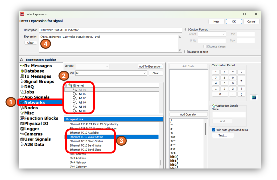
After selecting the control, and opening the Expression Builder , the following steps will bind the value of one of the TC10 properties to that control.
Select the Networks in the left pane.
Select one of the Automotive Ethernet networks as the source of the status. (In this case AE 01 is chosen)
In the properties pane, scroll down to the TC10 commands shown in the diagram above.
Adding this property to the expression will bind its value to the control.
Sending TC10 Commands from a Function Blocks
Function Blocks are scripts created in Vehicle Spy. The TC10 status of an Ethernet port can be referenced using the same interface as used for Graphical Panels and it can be used in the logical statements of a script. The TC10 sleep and wake requests can also be sent by using Function Blocks using the Set Value Command as shown below.
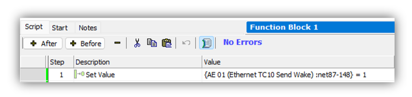
More info on the Function Blocks and their editor can be found in this section of the Vehicle Spy documentation.
The Set Value Command uses the same Expression Builder interface to write a value to a property.
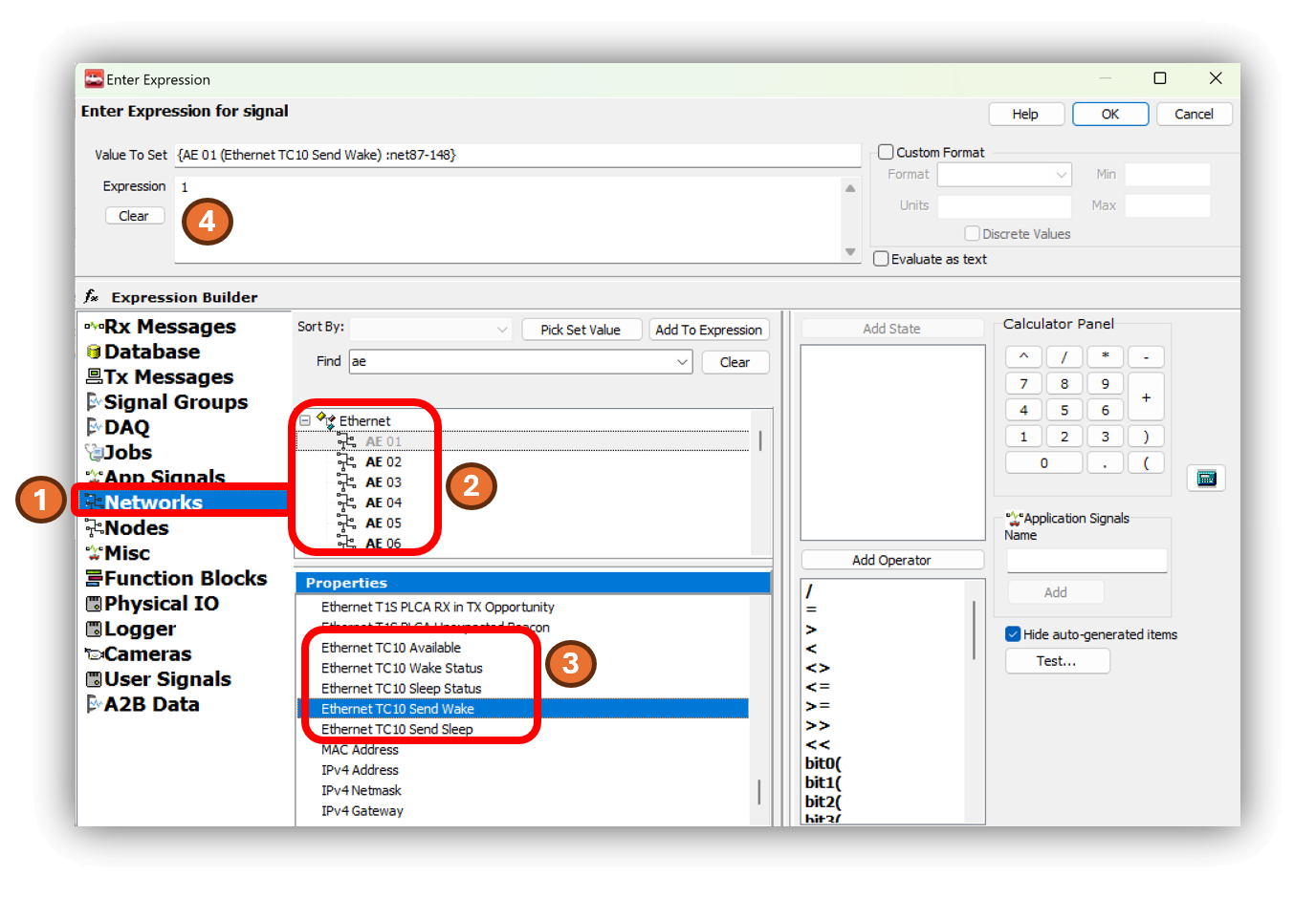
From this screen follow steps similar to the last example.
Select the Networks in the left pane.
Select an Automotive Ethernet networks to send the TC10 command. (In this case AE 01 is chosen)
In the properties pane, scroll down to the TC10 commands shown in the diagram above.
Select this Send Wake or Send Sleep property
as the value to set, and set the expression to 1.
8.4.2. Using TC10 with Intrepid’s Open Source APIs
libicsneo is the Intrepid Control Systems device communication library.
Installation and usage documentation can be found within each of the respective APIs.
TC10 C++ API
Download this C++ TC10 Example
to see the use of the following C++ functions.
TC10 Python API
Following are the equivalent TC10 functions for Python.
TC10 C API
Coming Soon!
TC10 is not supported in Intrepid legacy APIs
There is no support for TC10 in the neoVI API (icsneo40) or python_ics. Please consider using libicsneo or Vehicle Spy 3 .
If you are having trouble working with TC10 using any of the interfaces above, please contact our Customer Support