5. Installation & Configuration Guide
5.1. Physical Setup & Installation
Before connecting to software, ensure your hardware is physically secured and powered correctly.
5.1.1. Mechanical Assembly: Daisy-chaining
RAD-IO2 modules are designed to be modular. To expand your I/O capacity, physically link multiple units.
Daisy-chaining: Align the side connectors of two modules and slide them together until they click and use the USB to connect them together.
Jumper Plates: Secure the modules using the provided jumper plates and screws. This ensures mechanical stability and a consistent ground plane.
5.1.2. Power Management & USB Requirements
Powering a stack of modules depends on your USB host port capabilities.
USB 2.0 (500mA): Supports up to 2 modules.
USB 3.0+ (900mA+): Supports up to 5 modules.
Current Limits: If you exceed these limits, modules may flicker or fail to appear in the software. For larger stacks, use a powered USB hub or an Intrepid interface.
5.2. RAD-IO2 Configuration Utility
Each module type comes with a factory-preset Base CAN ID. If you have multiple modules of the same type in a daisy-chain, you must change the CAN ID of the additional units to avoid network conflicts.
Module Type |
Factory Default CAN ID (Hex) |
Description |
|---|---|---|
RAD-IO2-TC |
0x100 |
8-Channel Thermocouple |
RAD-IO2-AIN |
0x110 |
8-Channel Analog Input |
RAD-IO2-AOUT |
0x120 |
8-Channel Analog Output |
RAD-IO2-DIO |
0x130 |
8-Channel Digital I/O |
RAD-IO2-PWR |
0x140 |
Power Management/Monitoring |
Find Device: Connect your device via USB and click “Find Device.” The connected modules will populate in the list.

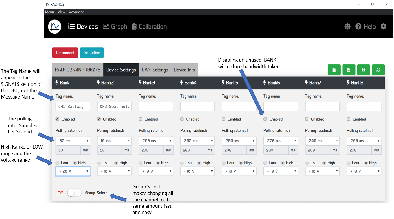
Configuration Parameters: Select a module to edit:
Tag Name: Label the bank for easy identification (e.g., “Engine_Temp”).
Sampling Frequency (SPS): Set the Samples Per Second for Analog and TC inputs.
Input Range: Toggle between High and Low voltage ranges.
Digital I/O: Set thresholds for inputs or PWM frequency/duty cycle for outputs.
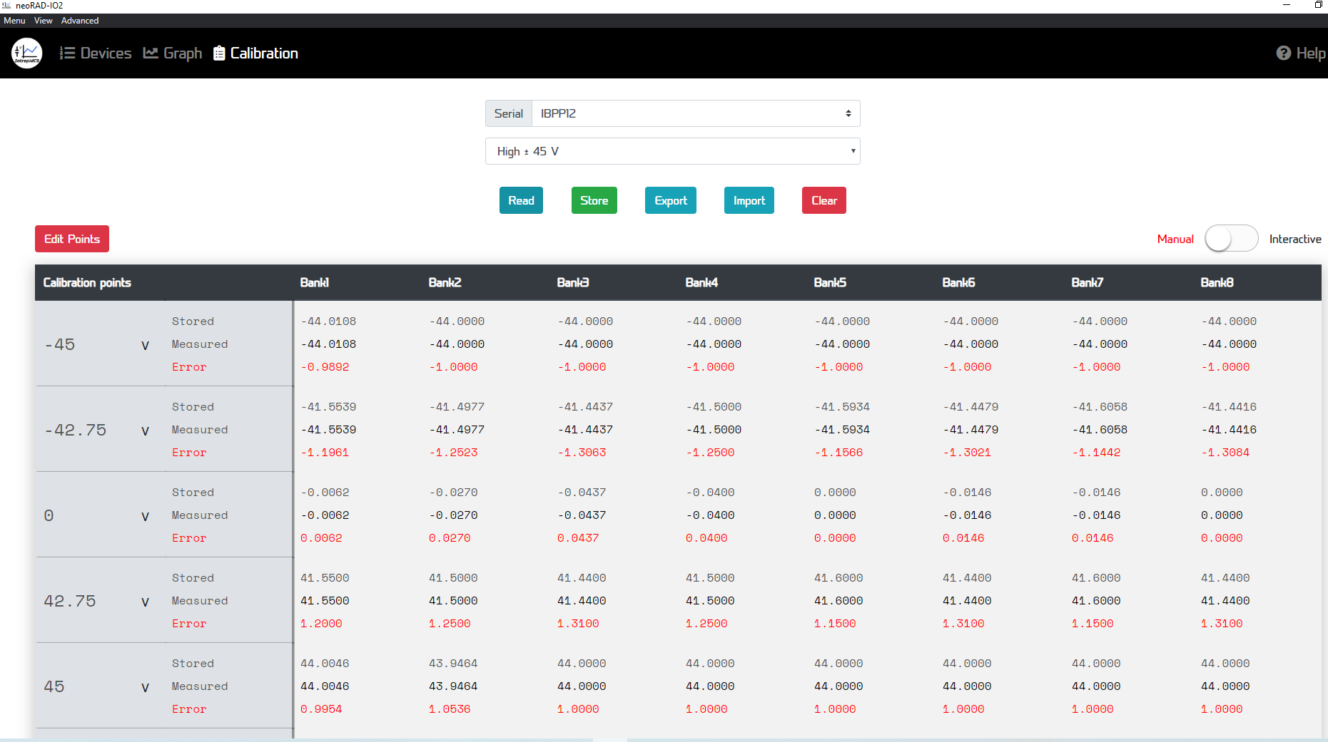
Calibration: Use the “Calibration” tab for manual or interactive offsets for Thermocouple and Analog modules.
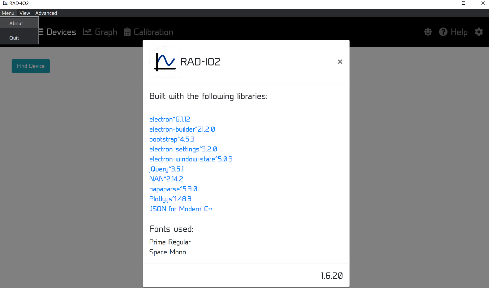
The top drop down menu selection is “Menu”; “View” and “Advanced”.
Clicking the “Menu” displays “Quit”, which ends the program and “About”, which displays a box with the libraries and the version. The source code for this project is on GitHub.
https://github.com/intrepidcs/libneoradio2
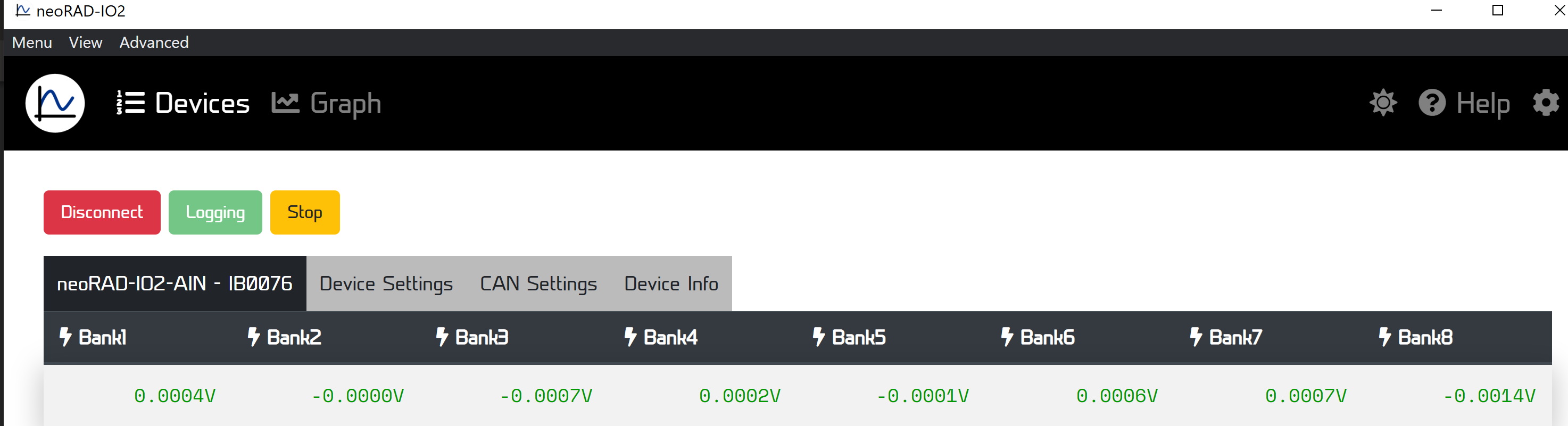
Run the configuration application and click “Go Online.” This allows for real-time data streaming and graphing directly on your PC. You can also integrate this data into your own software environment using the provided API for C++, Python, or JavaScript.
To move the RAD-IO2 to a vehicle network or Intrepid hardware:
Disconnect the USB-C cable from the PC.
For CAN-HUB: Connect the RAD-IO2 to the CAN-HUB via USB-C, then connect the DB9 to your CAN network.
For Intrepid Interfaces: Connect the RAD-IO2 USB-C directly to the USB host port on a FIRE, ION, or GigaStar.
Decoding: In Vehicle Spy, data will appear on the neoVI channel as native CAN data. You can export a DBC file from the configuration utility to decode these signals automatically.
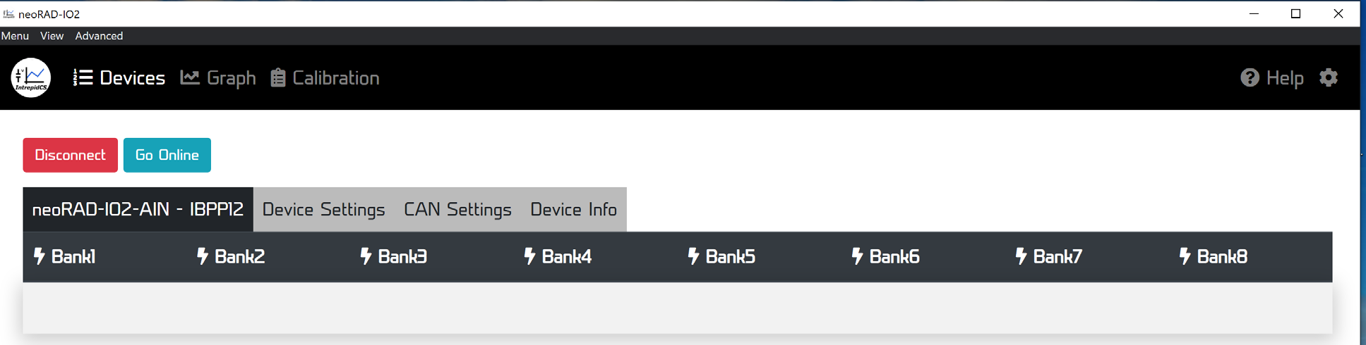
The ”Device Settings” TAB
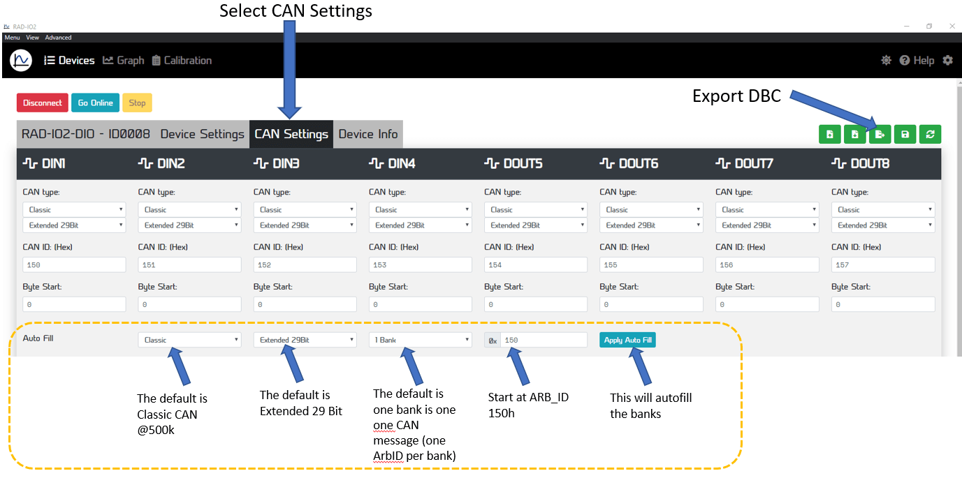
The CAN Settings tab allows the user to set CAN-ID and the CAN mode; either CAN or CAN-FD mode and the CAN-ID of each bank.
The CALIBRATION screen is somewhat complex and subject to change, there is currently an “Interactive Mode” and a “Manual Mode”. The target points can be changed by the user.
5.3. CAN-HUB Device Configuration
- Refer to this section if you need to update the CAN-HUB’s firmware or modify its settings. This includes procedures for:
Updating the Firmware
Configuring the CAN bus speeds
Adjusting the CAN bus termination
Setting the CAN Sleep ID Address
The CAN-HUB can only be updated via VIA Vehicle Spy and an Intrepid Control Systems CAN device.
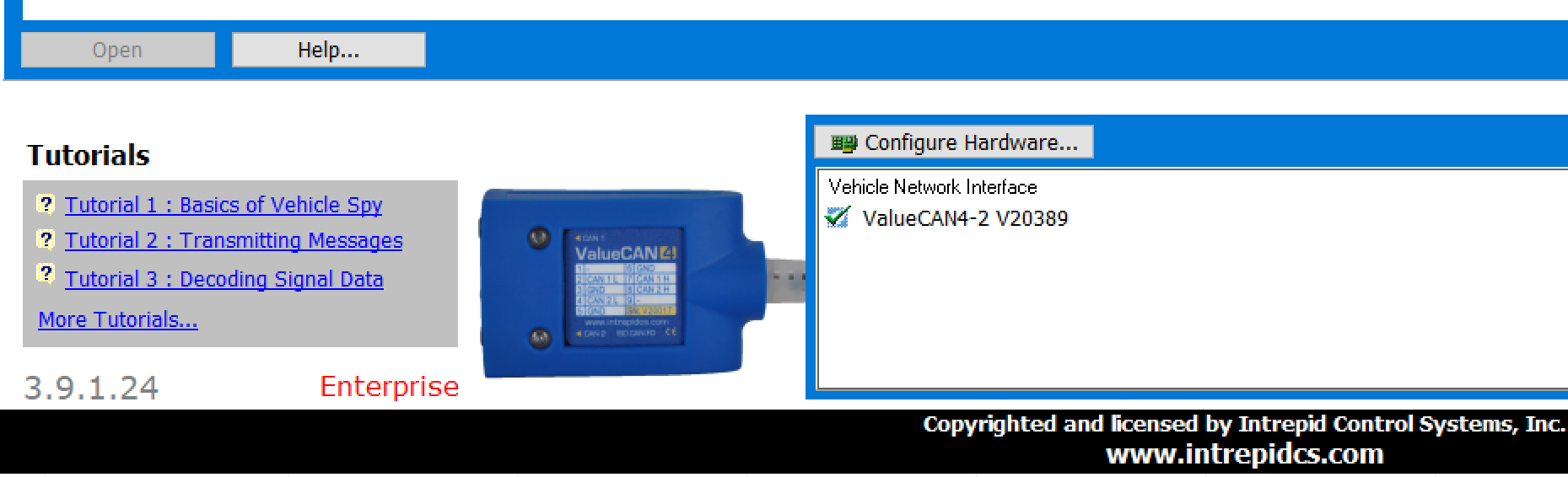
Open Vehicle Spy 3.
You will see the version number in the lower left corner (only 3.9.1.24 or above will work) and the level in red text (i.e. Basic, Pro, Enterprise and Enterprise Plus). This is the device connected to the computer via the USB cable that will program the RAD-IO2 over the CAN Bus.
Next, select “CoreMini Console” from the Tools pull-down menu and wait for the CoreMini Console window to open.
Hardware Setup: The initial screen will default on the NeoVI(USB) tab.
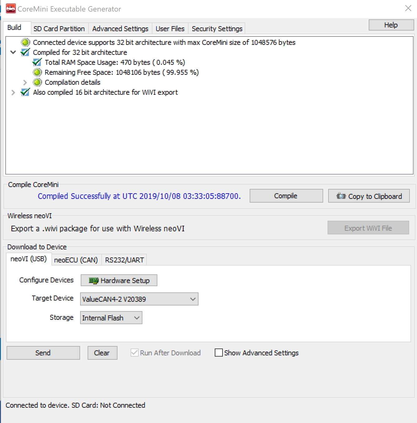
The neoVI Explorer window should pop-up.
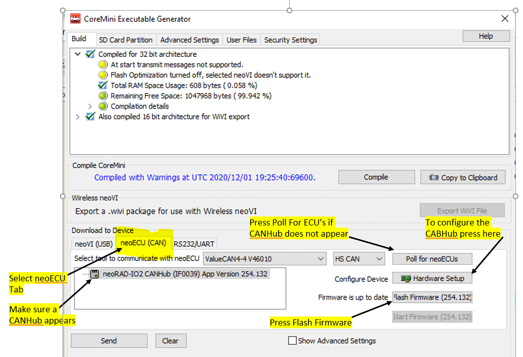
Click on the neoECU CAN tab
The RAD-IO2 CAN-HUB should be listed. If not, click on the “Poll for neoECU’s button”.
Select the CAN-HUB by clicking on it and click the “Flash Firmware” button to download the latest software.
If you need to configure the CAN-HUB then press Hardware setup. Refer to the screen shot below.
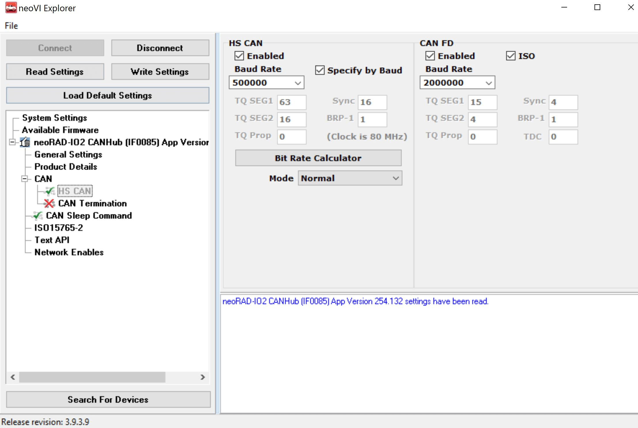
You will then get the neoVI explorer or ICS Device Manager for the CAN-HUB, which may be familiar to many.
Here you will be able to change the CAN and CAN-FD speed and the termination, and the CAN Sleep command, which is detailed on the next page.
DO NOT turn off CAN termination unless the CAN-HUB is in a CAN- Network that is already terminated.
A key feature of the CAN-HUB is its ability to halt all outbound CAN communication after a set, programmable period. This function, known as CAN-SLEEP, is vital for preventing connected CAN data loggers (such as ION or Fire series devices) from remaining active and potentially draining the vehicle’s battery.
It is important to note, however, that the RAD-IO2 hardware will continue to draw power from the CAN-HUB even when CAN-SLEEP is active. Therefore, it is highly recommended to power the CAN-HUB from a circuit that is only active when the vehicle’s ignition is on (a key-on circuit) to prevent battery drain.
The Arbitration ID (ARB-ID) used for the CAN Sleep command in the CAN-HUB can be configured on its dedicated screen; the factory default is 100h (29-bit extended ID).
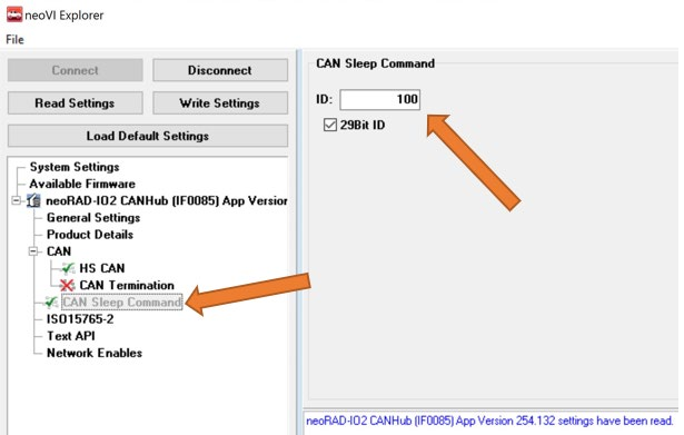
The CAN-HUB is put into sleep mode by sending the sleep ARB-ID (default is 100h). The second byte of this message specifies the sleep timeout duration in seconds.
To prevent the unit from sleeping, a periodic “keep-alive” or “arm” message must be sent before the specified timeout expires. If the timeout is reached without a keep-alive message, the CAN-HUB will stop transmitting RAD-IO2 messages.
To wake the CAN-HUB, simply send it any message. This action clears the sleep mode until it is explicitly invoked again.
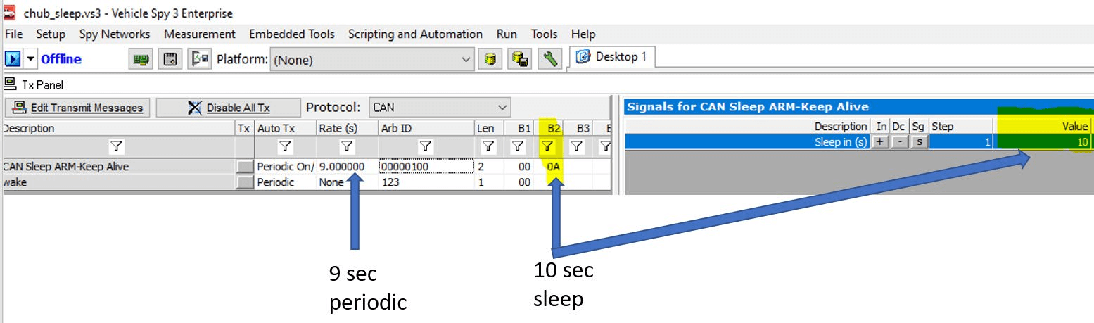
In the above example, the CAN-HUB can be sent a periodic message every 9 seconds with a 10 second expiration time. Therefore it will never go to sleep. If you were to stop the periodic message it will sleep 10 seconds after the last message is received.
5.4. Using the RAD-IO2 with Intrepid Hardware
The RAD-IO2 module communicates using a UART/USB signal. This signal can be connected directly to the USB port of an Intrepid device. Alternatively, the native UART/USB signal can be converted to CAN messages using the CAN-HUB.
Configuration and Integration:
The Arbitration CAN IDs for the messages can be set individually for each channel or as a group.
Configuration can be accomplished using the free JAVA program or custom Python code https://github.com/intrepidcs/libneoradio2 , both available on GitHub.
When using software like Vehicle Spy, you should load the DBC file (generated by the free software from our GitHub page) associated with the specific channel. If the DBC file is not loaded, you must manually configure the receive channels.
Note on Connection Channel Selection:
If using the CAN-HUB, select the appropriate “DWCAN” channel.
If connecting directly to the Intrepid device via USB, select the “NEOVI” channel.
Example: Configuring Receive Messages for Input Devices
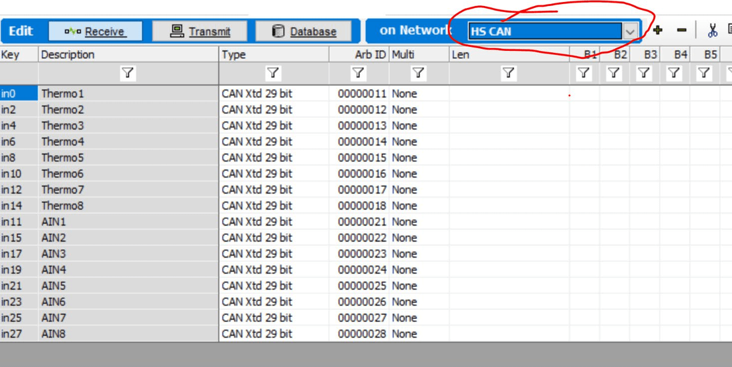
Create a Receive message using the Messages Editor by clicking “Receive.”
CAN-HUB Connection: Select the appropriate HS-CAN channel that you have physically wired or connected the DB9 connector on the CAN-HUB output to. The CAN-HUB requires 5-40VDC power, supplied either through a custom cable or a cable sold by Intrepid.
Direct USB Connection (FIRE2/ION/Plasma or Industrial Value CAN): Select the NEOVI channel.
DWCAN EXAMPLE

Configuring VSPY for RAD-IO2
The setup for VSPY differs only in the “on Network” selection, depending on your connection:
CAN-HUB Connection: Select the appropriate HSCAN bus for the RAD-IO2-AOUT.
Direct USB Connection (FIRE2, ION/Plasma, or Industrial VCAN): Select NEOVI.
Setting up a 32-Bit Receive Signal:
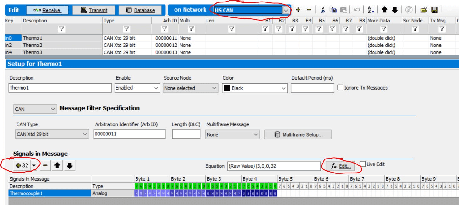
Set up the Receive signal as 32 Bits.
Press the “fx Edit” button.
Select “32 Bit Floating IEEE Float” and “Little End First …”.
Note: Optionally, you can set Min and Max values. This only affects future Graphical Panels and does not impact the output measurements.
Your signal measurements will now display as decimal values.
5.5. Configure RAD-IO2-AOUT - Analog Output Module
The RAD-IO2-AOUT module provides 8 banks, each containing 3 isolated 0-5VDC 16-bit DAC channels, for a total of 24 analog output channels.
Configuration
Connection: When using the AOUT module with a CAN-HUB, select the appropriate HSCAN bus. If connected directly via USB to an Intrepid device, use NEO-VI.
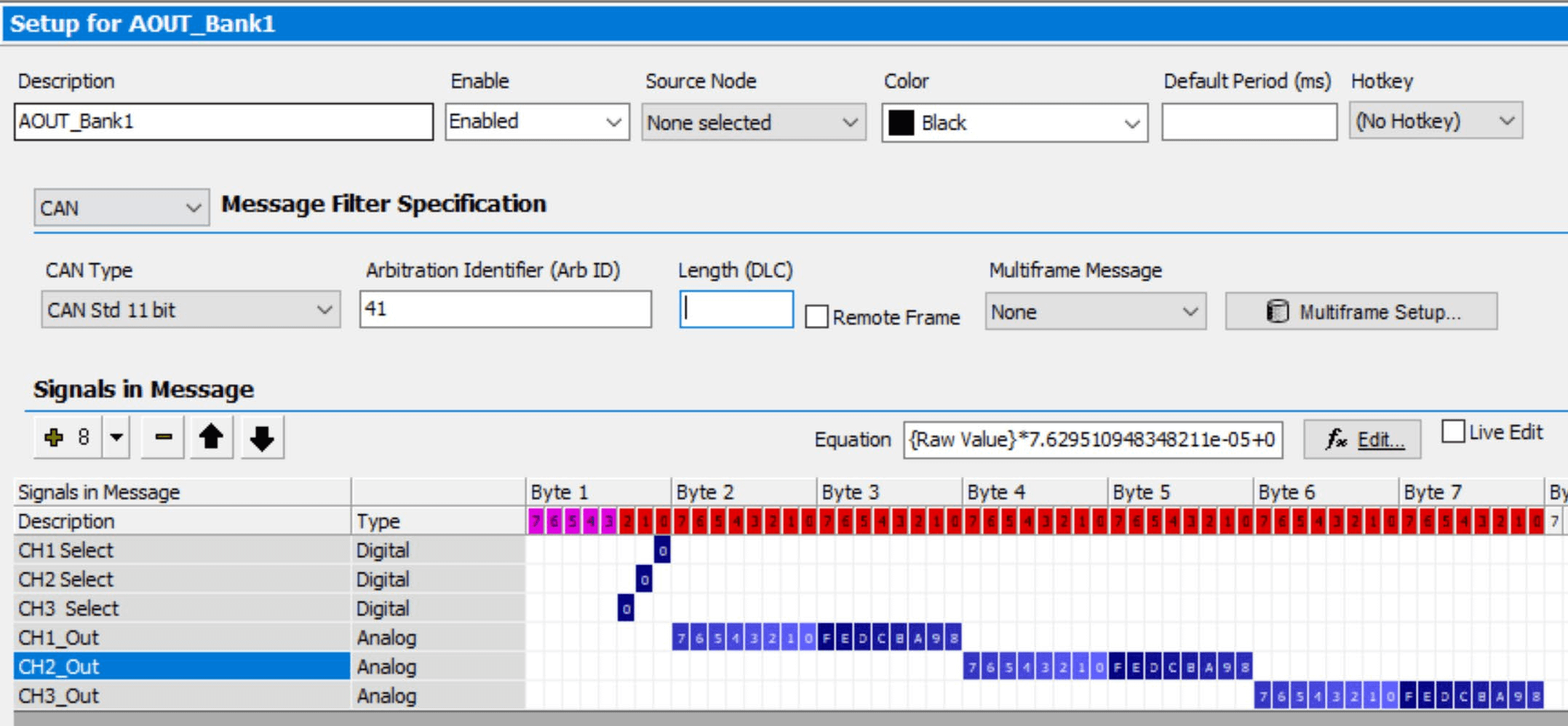
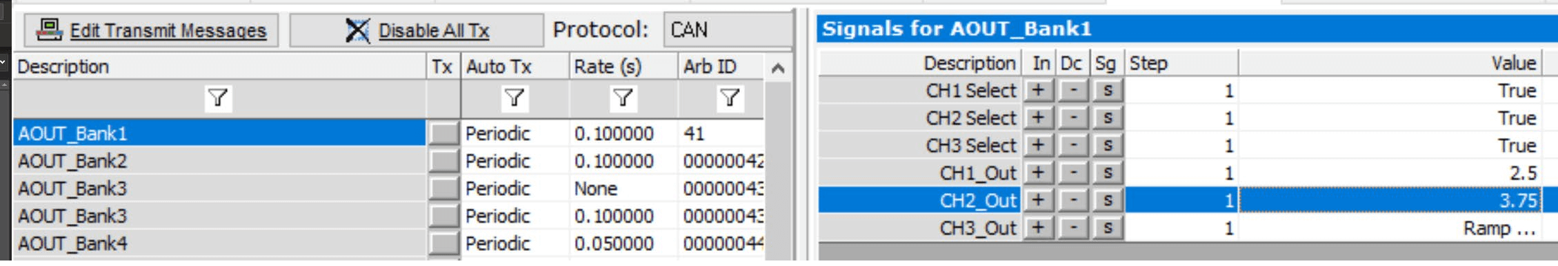
Addressing: The Analog Output examples assume a base Arbitration ID (ARB-ID) range of 41h to 48h (41h for Bank 1, 48h for Bank 8).
Generating Analog Output Values
To understand how the system works, if you wanted to generate 2.5 volts using hex you would need to send 7F,FF. Desired voltage divided by Full scale voltage multiplied by 16 bits. Therefore 2.5 / 5 * 65535 = , or 32767.5; truncating to 32767 is 7FFF hex. 1 Volt would be 1 / 5 * 65535 = 13,107 = 3333 hex
In the first byte, the LSB bits 1,2,3 are the enable selector for each AOUT, then the subsequent 2 bytes (16 bits) are for the actual analog output.
Keep in mind the Analog Output has three 0-5VDC 16 Bit DAC channels for each bank, for a total of 24 channels, and each bank is isolated from each other bank.
In this example the CH1,CH2 and CH3 are the selection mask. CH1_Out, CH2_Out, CH3_Out are the data bytes.
FOR EXAMPLE: If you wanted to send 2.5 VDC to Bank1 channel 1 you would need to transmit ARB-ID 0041 Byte1=01, Byte2=7F Byte3=FF.
DBC File/Tx Messages: Use a generated DBC file or your own transmit messages. For signals, you can use the VSPY Tx Panel to generate functions like RAMP (e.g., 2.5 VDC, 3.75 VDC).
Function Blocks: Use the SET VALUE and Transmit command function blocks within a script or setup.
This example assume ARB ID 41h-48h
CH Select |
Channel 1 |
Channel 2 |
Channel 3 |
|||||
ARB ID |
Byte1 |
Byte2 |
Byte3 |
Byte4 |
Byte5 |
Byte6 |
Byte3 |
|
41 |
0 |
7F |
FF |
No Channel selected, Error response |
||||
41 |
1 |
7F |
FF |
Bank1, CH1, 2.5 VDC |
||||
41 |
1 |
FF |
FF |
Bank1, CH1, 5 VDC |
||||
41 |
1 |
0 |
0 |
Bank1, CH1, 0 VDC |
||||
41 |
2 |
0 |
0 |
7F |
FF |
Bank1, CH2, 2.5VDC |
||
41 |
4 |
0 |
0 |
0 |
0 |
FF |
FF |
Bank1, CH2, 2.5VDC |
42 |
1 |
7F |
FF |
Bank1, CH2, 2.5VDC |
||||
45 |
3 |
33 |
33 |
7F |
FF |
Bank5, CH1, 1VDC; CH2 2.5 VDC |
||
48 |
7 |
33 |
33 |
7F |
FF |
FF |
FF |
Bank8, CH1, 1VDC; CH2 2.5 VDC, CH3 5VDC |
48 |
7 |
0 |
0 |
0 |
0 |
0 |
0 |
Bank5, CH1, 1VDC |
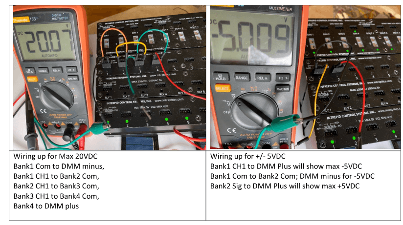
It is simple to achieve a voltage greater than 5VDC, or even a negative polarity, by connecting the signal and ground pins of the isolated banks so that the resulting total voltage is the sum of the individual voltages.
5.6. Configure RAD-IO2 RELAY Module
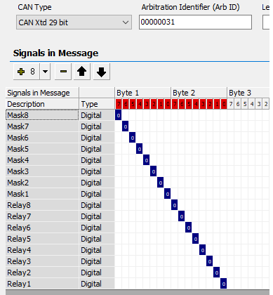
The RELAY module uses a two-byte logic: Byte 1 serves as the selector or mask, and Byte 2 contains the data.
To control a specific relay, the corresponding bit in Byte 1 must be set to HI (“1”) to enable the mask. Simultaneously, setting the corresponding bit in Byte 2 to HI (“1”) will turn the relay ON.
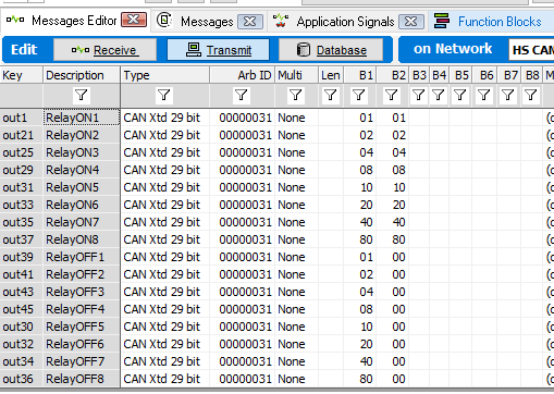
Example (Assuming ArbID h0031 for the Relay module):
Turn Relay 1 ON: Transmit
h0031,01,01. (Byte 1, bit 1 enables the mask; Byte 2, bit 1 sets the data to ON).Turn Relay 1 OFF: Transmit
h0031,01,00. (Byte 1, bit 1 enables the mask; Byte 2, bit 1 sets the data to OFF).
Note: Transmitting h0031,00,00 will have no effect on the relay state and will instead trigger a response message from the Relay module.
Relay Output Example
Assume ARBID 0031h
Byte1 |
Byte2 |
|||
Transmit 31h |
0 |
0 |
You will receive a message back from the module, nothing will turn ON |
|
Transmit 31h |
1 |
1 |
Relay 1 will turn “ON” |
|
Transmit 31h |
1 |
0 |
Relay 1 will turn “OFF” |
|
Transmit 31h |
80 |
80 |
Relay 8 will turn “ON” |
|
Transmit 31h |
80 |
0 |
Relay 8 will turn “OFF |
|
Transmit 31h |
1A |
1A |
Relay 2,4,5 will turn on |
|
Transmit 31h |
1A |
0A |
Relay 5 will turn OFF and relays 2,4 ON |
|
Transmit 31h |
1 |
FF |
Relay 1 will turn ON, there will be no effect on the other relays |
For example, 16 signals were created to demonstrate control over the relays.
To improve the readability of function blocks for both current and future users, it is recommended to create separate Transmit Messages for each relay. Additionally, creating application signals for each value can further enhance clarity.
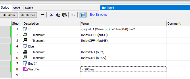
This function block example controls Relay 1 and Relay 4 based on the voltage measured by the AIN module.
If the measured voltage is greater than or equal to 2 volts, Relay 1 and Relay 4 are turned OFF.
Otherwise (if the voltage is less than 2 volts), Relay 1 and Relay 4 are turned ON.
A 200 mS delay is included after the relay state changes. This delay is important to prevent relay “chatter,” which can occur if the input signal used to trigger the action is noisy.
5.7. Configure RAD-IO2 DIO Module
Digital Input Settings
Note: Digital inputs share two settings: Pre-scaler and Trip Voltage. All channels use the values set for channel 1.9.1.1 Pre-scaler (Clock Divider)
The Pre-scaler acts as a clock divider on the 1.2MHz main clock and determines the measurable frequency range:
Pre-scaler = 200: Measures frequencies from 1 Hz to 200 Hz.
Pre-scaler = 20: Measures frequencies from 10 Hz to 2 kHz.
Pre-scaler = 1: Measures frequencies from 100 Hz to 20 kHz.
A higher Pre-scaler value allows for measuring slower periods but limits the ability to measure short periods. The Pre-scaler can be adjusted “on the fly” to accommodate measurement needs.
Trip Voltage
The Trip voltage sets the threshold used to distinguish high input values from low input values.
Invert Bit
Each channel includes an invert bit, which inverts the resulting input. For example, if the PWM output is 20%, setting the Invert bit will invert the result to 80%.
The Digital Input (DI) has six configurable modes, which can be dynamically changed during operation. This flexibility allows the same physical input to be sequenced through different measurement types, such as Analog In, PWM, and frequency.DI Operating Modes
Mode Name |
Description |
Value Interpretation |
Notes |
|---|---|---|---|
RADIO2DIN_MODE_DISABLE |
Disables the channel. |
No values are returned. |
|
RADIO2DIN_MODE_DIGITAL |
Returns the digital state of the input as a single byte. |
0x00 = Input Low; 0x01 = Input High. |
These values are reversed if the ‘invert’ setting is 1. |
RADIO2DIN_MODE_PWM |
Returns the PWM duty cycle of the input as a single byte (0 to 100%). |
Result is the duty cycle percentage. |
If ‘invert’ is set, the result is 100 minus the duty cycle. |
RADIO2DIN_MODE_PERIOD |
Returns the high period of the last pulse as a 16-bit integer. |
Period (seconds) = (value * prescaler) / 1,200,000 |
The prescaler value can be used to measure longer pulses. The ‘invert’ bit switches the measurement to the low-time period. |
RADIO2DIN_MODE_FREQ |
Returns the frequency of the signal as a 16-bit value. |
Frequency (Hz) = value / prescaler |
|
RADIO2DIN_MODE_ANALOG |
Returns a 12-bit value for the input voltage. |
Voltage (Volts) = (value * 40) / 4,096 |
Digital Output (DO)
The RAD-IO-DIO module features digital outputs organized into four separate banks.
Bank Power Input
PIN1 serves as the power input for each bank, supplying power to Channel A, Channel B, etc., within that bank.
Signals:
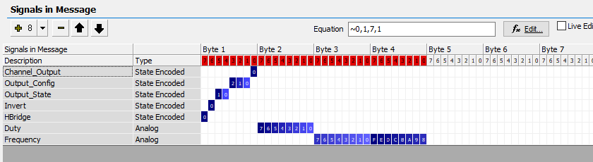
Digital Output Configuration Details
This section outlines the parameters used to configure the Digital Output (DO) channels, including channel selection, H-Bridge mode, output configuration, H-Bridge states, frequency, and duty cycle.9.4.1 Channel Selection (Channel_Output)
Control Byte: Byte 1, Bit 0
Purpose: Selects between Channel A or Channel B output control.
Channel A: Set Byte 1, Bit 0 = “0”
Channel B: Set Byte 1, Bit 0 = “1”
Note: If the H-Bridge is configured as a full bridge (see 9.4.2), only Channel A values will be accepted, and Channel B settings are ignored.
H-Bridge Configuration
Control Byte: Byte 1, Bit 7
Purpose: Joins the two Half Bridges to form a Full H-Bridge.
Full H-Bridge: Set Byte 1, Bit 7 = “1” (Channel B settings are ignored in this mode).
Digital Output Modes (Output_Config)
The Digital Output (DO) has four operational modes, controlled by specific bits in the configuration byte:
Disabled (RADIO2DOUT_SET_HIZ):
Effect: The output is disabled, and the Digital Outputs do not change state.
Control: Byte 1, Bit (The bit number is missing in the original text, but the mode is equivalent to RADIO2DOUT_SET_HIZ).
Simple Digital Output (DO):
Effect: Sets the output to a simple ON or OFF digital state.
Pulse Width Modulation (PWM):
Effect: Sets a duty cycle (0-100%) and a frequency (0 Hz to 65535 Hz).
Period or Oneshot:
Effect: Sends a single pulse. The configuration value sets the pulse length in milliseconds.
H-Bridge Output States
There are four specific output states available for the H-Bridge.
RADIO2DOUT_SET_HIZ(High Impedance):Value: 0
Effect: The equivalent of Disabled. Outputs are not driven.
RADIO2DOUT_SET_LOW_REV(Low/Reverse):Effect: OUT1 is low and OUT2 is high, causing a motor to spin in reverse.
RADIO2DOUT_SET_HIGH_FWD(High/Forward):Effect: OUT1 is high and OUT2 is low, causing a motor to spin forwards.
RADIO2DOUT_SET_BRAKE(Brake):Effect: All outputs are set low. This shorts the windings of a connected motor, causing the magnetic fields to collapse and stopping the motor much faster than the HiZ state.
Frequency
Format: 16-bit value in Hz.
Range: 0 Hz to 65535 Hz.
Duty Cycle
Format: 8-bit value in percent (%).
Accepted Range: 0% to 100%.
Granularity: 1% (The 8-bit value range of 0-255 allows for high resolution, but only 0-100% is used for duty cycle).
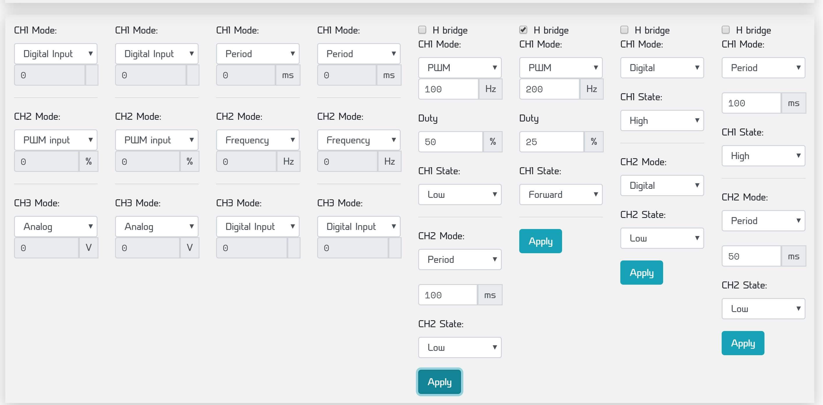
The DIO module’s functionality, including control over Inputs and Outputs, is managed through the graphical user interface (GUI) program.
Input Configuration
Each DIO INPUT bank contains three channels. These channels are highly configurable and can be set to function as:
Digital Input
Analog Input
Period
Frequency
For instance, within a single bank, Channel 1 could be configured as a Digital Input, while Channel 2 is set to PWM and reports a frequency.
Output Configuration
Each DIO OUTPUT bank offers flexible configuration options:
Bridge Type: Half Bridge or Full Bridge
Mode: Digital Output, PWM, or Period
State: HIZ, Forward, Reverse, or Brake
Important Note on Output State: The default STATE is HIZ (High Impedance), meaning no output will be generated in this mode. The Brake mode is specifically used to short out the H-Bridge for quicker motor stopping.