4. Physical Setup & Installation
This section covers the mechanical and electrical integration of the RAD-IO2 modules into your testing environment.
4.1. Mechanical Assembly: Daisy-chaining and Jumper Plates
RAD-IO2 modules are designed to be modular. You can expand your I/O capacity by physically linking multiple units together.
Daisy-chaining: Align the side connectors of two modules and slide them together until they click. This establishes the internal communication bus between units.
Jumper Plates: Use the provided jumper plates and screws to secure the modules together. This ensures mechanical stability and maintains a consistent ground plane across the stack.
4.2. Configuration A: Direct-to-PC (USB Mode)
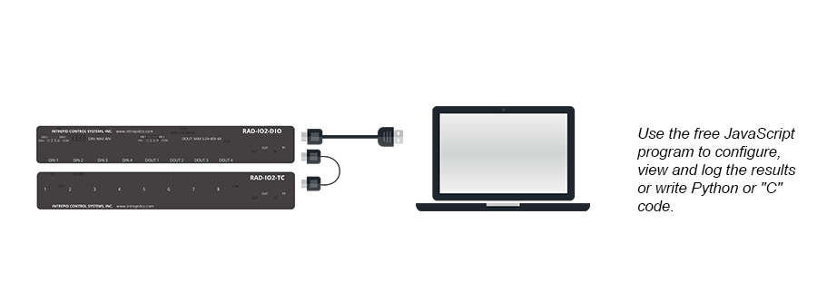
In this mode, the RAD-IO2 acts as a standard USB peripheral. This is the simplest setup for bench testing or standalone data logging.
Connection: Plug the RAD-IO2 directly into the PC or Mac (Windows or Linux supported) using a high-quality USB-C cable.
Software: Run the Free RAD-IO2 Software (Mac, Linux, and Windows) or RAD-IO2 GUI Interface (GitHub) on your computer. This tool allows you to:
Configure individual module settings.
Control module outputs.
View real-time data via a simple graphing interface.
Custom Code: For advanced users who prefer to bypass the default JavaScript application, direct module programming is supported. You can utilize the provided API with your own software.
Available resources include:
Python: RAD-IO2 Python API and Examples (GitHub), RAD-IO2 Python Documentation
Arduino Example: RAD-IO2 and Arduino Example (GitHub)
4.3. Configuration B: CAN-HUB Integration (Network Mode)
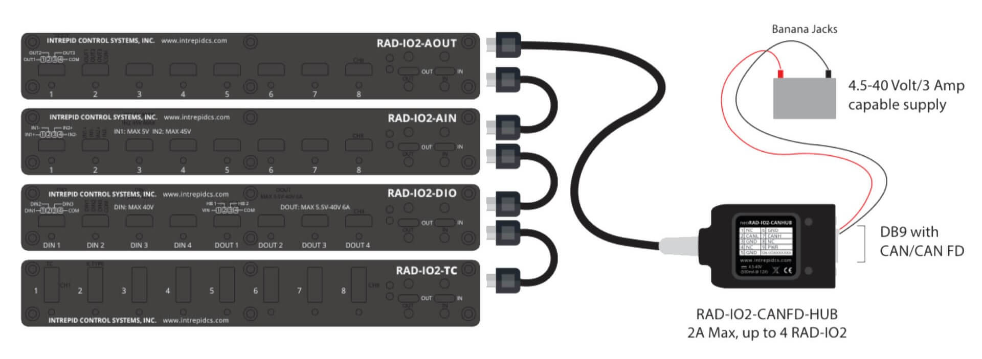
This configuration converts the RAD-IO2 into a CAN-based device, allowing it to reside on a vehicle network or interface with Intrepid or any CAN or CAN FD network adapters.
4.3.1. Using the CAN-HUB
Disconnect: Remove the USB cable from the PC and the USB-C port on the RAD-IO2.
Bridge: Connect the USB-C cable of the CAN-HUB to the RAD-IO2.
Network Connection: Connect the DB9 connector on the CAN-HUB to your CAN network or device.
Data Handling: Treat all incoming and outgoing data as standard CAN frames. Use your preferred software (Vehicle Spy, custom scripts, or third-party tools) for decoding.
4.3.2. Integration with Intrepid Interfaces
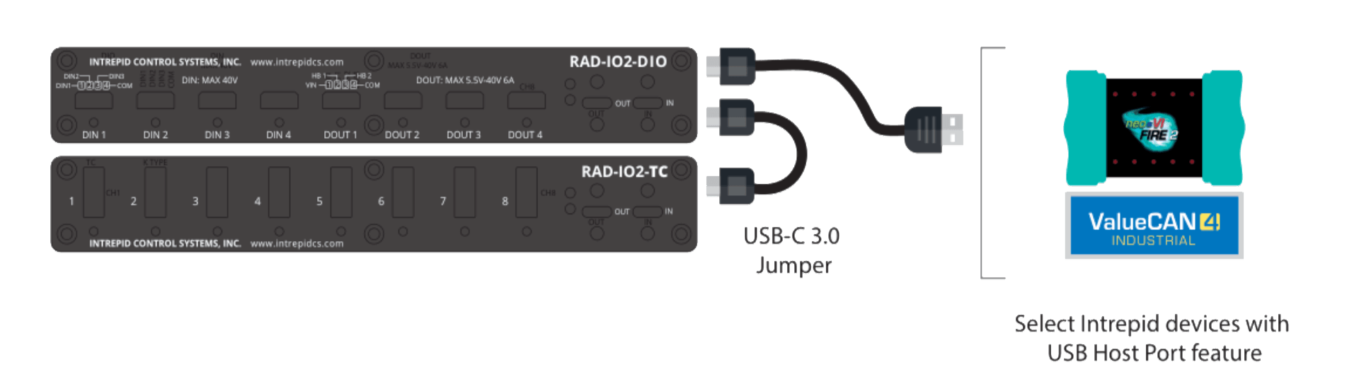
If you are using hardware such as the FIRE2, ION, ValueCAN4 Industrial.
Connect the USB cable from the RAD-IO2 directly to the USB host port on the Intrepid interface.
In Vehicle Spy, navigate to the neoVI channel. The software will treat the RAD-IO2 data as native CAN data for seamless logging and analysis.
4.4. Power Management: Current Limits and USB Requirements
Powering a stack of RAD-IO2 modules requires attention to the host port’s capabilities.
USB 2.0 vs. 3.0: USB 2.0 ports typically provide up to 500mA. This is usually sufficient for 1-2 modules.
USB 3.0+ ports provide up to 900mA or more, which is recommended for larger daisy-chained stacks (3+ modules).
Current Limits: If the total current draw of your stack exceeds the port limit, the modules may disconnect or fail to initialize.
Daisy-chain Limit: While physically you can connect many modules, we recommend a maximum of 5 modules per single USB power source to ensure signal integrity and power stability.